
Optical fiber grating sensor wave length measuring system

A technology of wavelength measurement and fiber grating, which is applied in the field of measurement, can solve the problems of expensive equipment, achieve the effect of less components, easy implementation, and cost reduction

Inactive Publication Date: 2007-01-03
BEIJING FBGTECH OPTOELECTRONICS TECH
View PDF0 Cites 12 Cited by
  • Summary
  • Abstract
  • Description
  • Claims
  • Application Information

AI Technical Summary

Problems solved by technology

For multi-channel sensor networks, in order to realize the processing of large-scale sensor network data, it is necessary to use some corresponding complex equipment, but the cost of these equipment is usually relatively expensive, how to reduce costs, improve measurement accuracy, meet real-time measurement, etc. Under the premise of all aspects, it is also a key consideration for researchers to achieve the optimal matching of various parts and meet the practical needs of fiber grating sensing systems in various fields of modernization.

Method used


Image

  • Optical fiber grating sensor wave length measuring system
  • Optical fiber grating sensor wave length measuring system
  • Optical fiber grating sensor wave length measuring system

Examples


Embodiment Construction

[0033] The present invention will be further described in detail in conjunction with the accompanying drawings and embodiments.

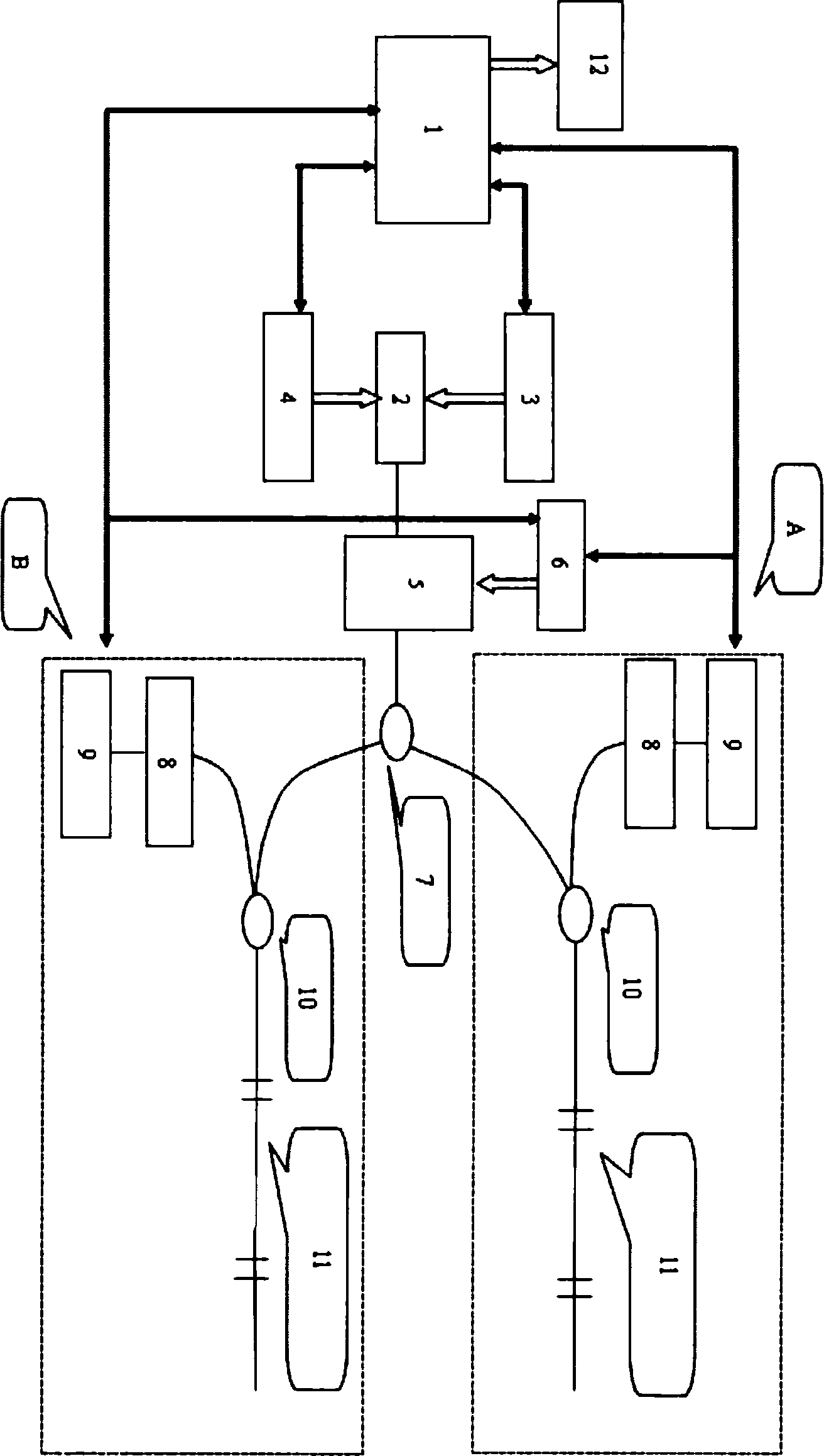
[0034] The following takes two channels as an example to illustrate the realization of the wavelength measurement of the fiber grating sensor. Its schematic diagram is as follows figure 1 shown. Among them, 1 represents the microprocessor, 2 represents the DFB laser, 3 represents the current tuning circuit, 4 represents the temperature tuning circuit, 5 represents the electro-optic modulator, 6 represents the modulation circuit, 7 represents the 1×N splitter, 8 represents the photoelectric detection module, 9 represents a high-speed sampling circuit, 10 represents a 1×2 splitter, 11 represents a fiber grating sensor network under test, and 12 represents an LCD display.

[0035] The system consists of two parts, A and B, consisting of DFB laser 2, temperature tuning circuit 4, current tuning circuit 3, modulation circuit 6, photoelectric modulator ...


PUM


Abstract

A fiber grating wavelength measuring system consists of the DFB laser, the temperature tuning circuit, the current tuning circuit, the photo-electricity modulator, the modulating circuit, the photo-electricity detector module, the high-speed sampling circuit, the microprocessor, the display part, the branching unit and the connecting fiber. The invention is: the DFB laser measures the wavelength of the fiber grating sensor that not only reduces the cost, but also uses to examine temperature, stress of building, emergency measurement, and the entire situation fitting for the measurement of the fiber grating sensor.

Description

technical field [0001] The invention belongs to the measurement field, in particular to a measurement system for measuring the wavelength of a fiber grating sensor. Background technique [0002] With the development of optical communication technology, some technologies in optical communication gradually provide a technical platform for applications in the sensing field, and fiber grating is one of them. With the continuous improvement of the manufacturing technology of fiber gratings, people's research on fiber gratings in light sensing has become more extensive and in-depth, and fiber grating sensors based on fiber grating technology are becoming another hot spot in the field of sensor research. . [0003] Compared with traditional electrical sensors, fiber grating sensors have very obvious technical advantages in sensor network applications: [0004] 1) The optical fiber grating sensor adopts all-optical measurement, which can realize longer-distance measurement without...

Claims


Application Information

Patent Timeline
Patent Type & Authority Applications(China)
IPC IPC(8): G01J9/00G01D18/00
Inventor 张碧华
Owner BEIJING FBGTECH OPTOELECTRONICS TECH
Learn More