Liquid cyclone

A liquid cyclone, the main body technology, applied in the direction of the cyclone device, the liquid degassing, the device in which the axial direction of the cyclone can be reversed, etc. Mix-in prevention effect

Active Publication Date: 2007-01-10
NIHON SPINDLE MFG CO LTD
View PDF2 Cites 8 Cited by
  • Summary
  • Abstract
  • Description
  • Claims
  • Application Information

AI Technical Summary

Problems solved by technology

[0005] However, the swirling flow F of the rising cleaning liquid passes through the mesh from the lower part to the upper part of the gas-liquid separation pipe 9 and becomes a spray flow ejected toward the radial direction. The lower part is stronger and the upper part is weaker, so as shown in the figure As shown by the arrow, it becomes a swirling flow directed toward the bottom surface of the upper casing 3 → the side wall surface → the gas-liquid separation pipe 9, so that the air after gas-liquid separation discharged into the upper casing 3 will flow in the A part of Fig. 10 In the process of spiraling up in the gas-liquid separation pipe 9, micro-bubbles will be discharged from the mesh together with the cleaning liquid, so there is a disadvantage of foaming from the cleaning liquid.

Method used


Image

  • Liquid cyclone
  • Liquid cyclone
  • Liquid cyclone

Examples


Embodiment 1

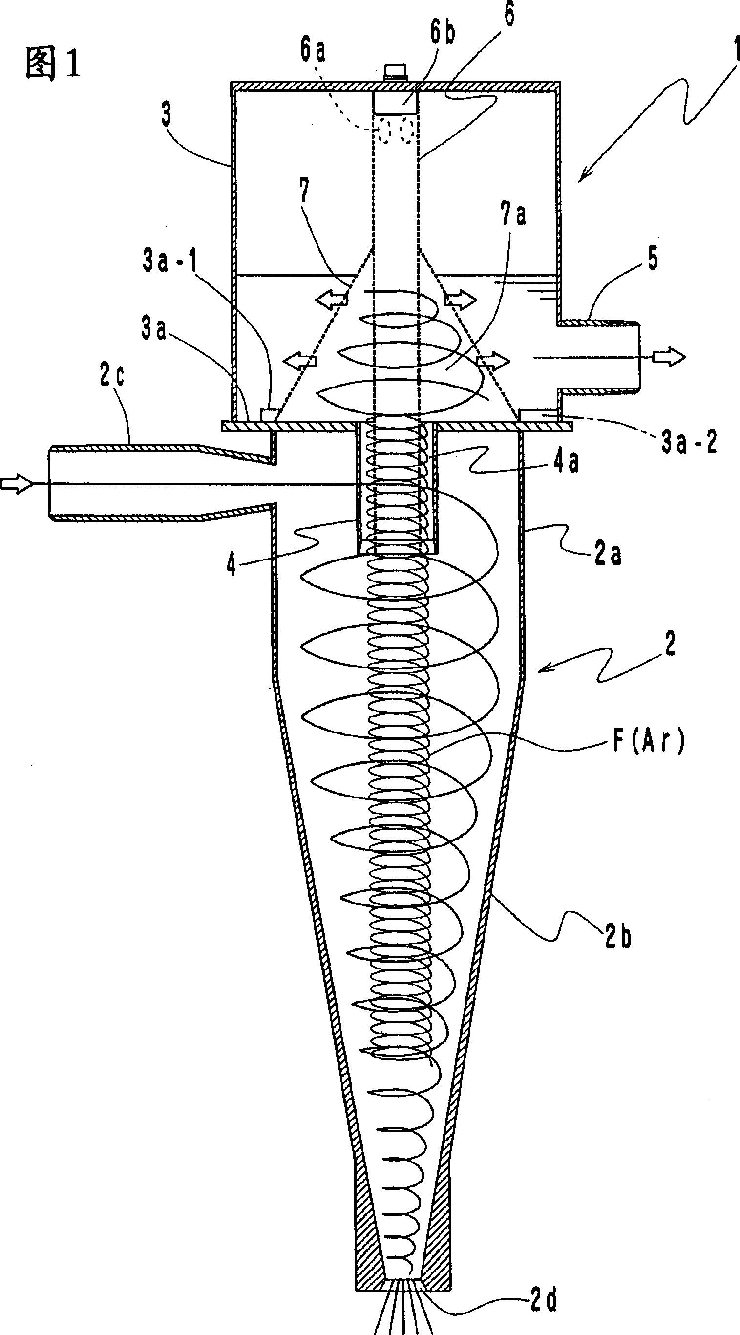
[0035] Fig. 1 shows a first embodiment of the liquid cyclone of the present invention.

[0036] In this liquid cyclone 1, a cylindrical body 6 having a net-shaped peripheral surface is inserted from the upper case 3 with a gap in the inner peripheral portion of the outlet pipe 4 connected to the upper case 3, and, The outflow damper 7 a is formed by a mesh-like umbrella 7 surrounding the inner protrusion of the upper casing 3 of the aforementioned cylindrical body 6 .

[0037] The cylindrical body 6 may be formed by rolling a mesh-like (metal mesh, etc.) plate into a cylindrical shape, or a porous plate (punched metal, etc.) or a cylindrical body formed with slits or the like may be used. In addition, the upper end of the cylinder 6 is mounted on the pin 6b, and the lower end is inserted into the inside of the outlet pipe 4. The pin 6b is fixed on the upper surface of the upper casing 3 and concentric with the outlet pipe 4 by a fixing mechanism such as a bolt.

[0038] At th...

Embodiment 2

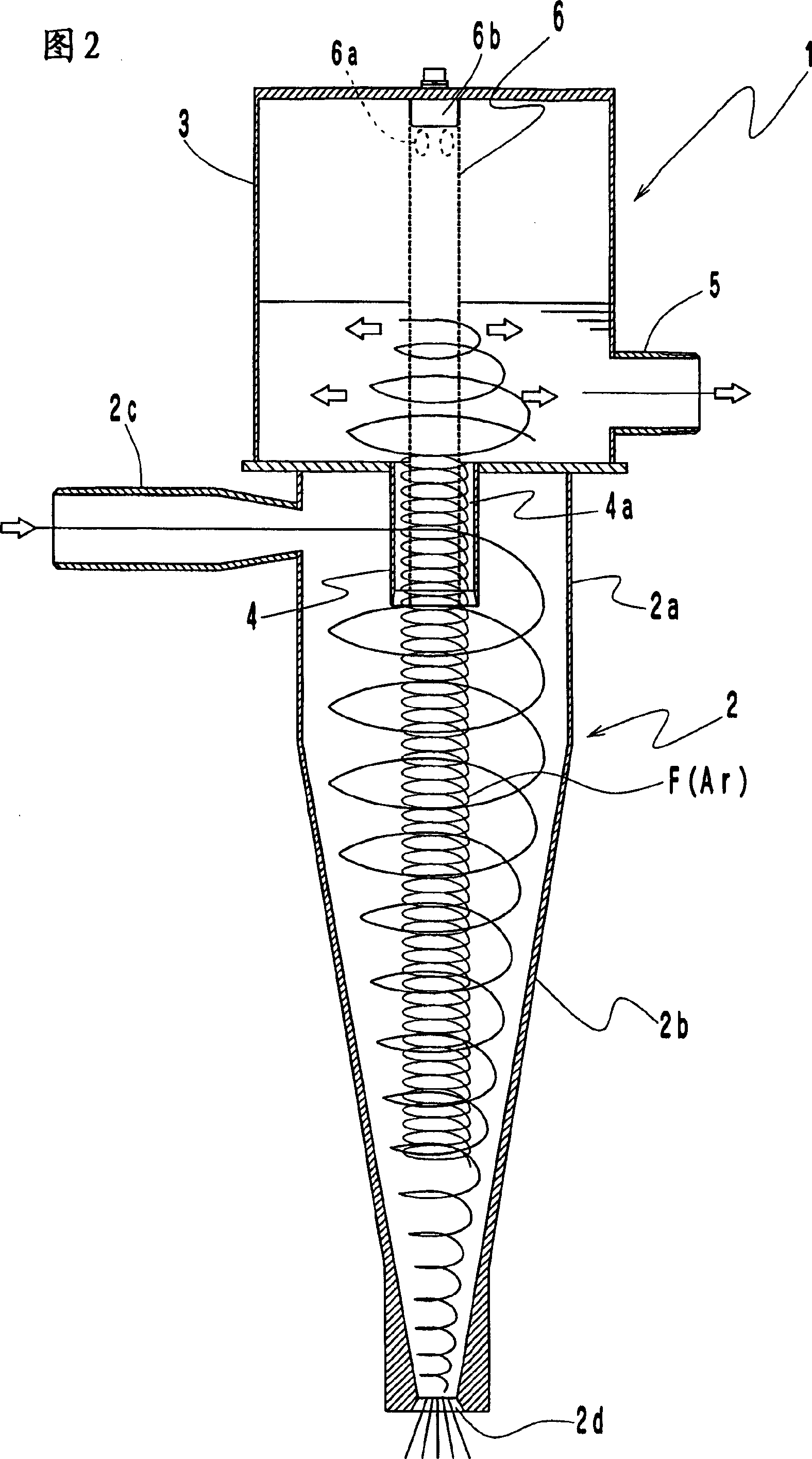
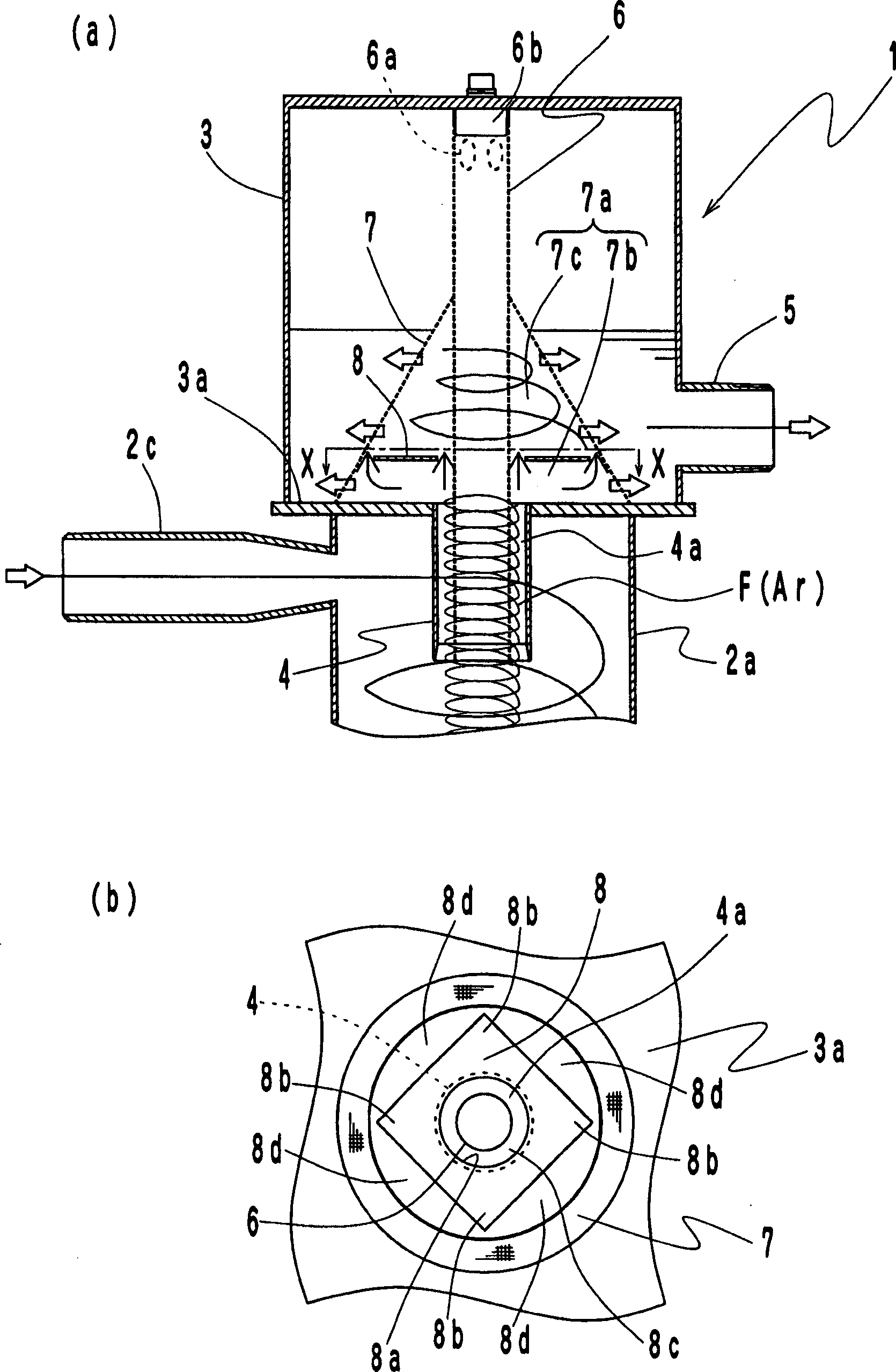
[0051] image 3 A second embodiment of the liquid cyclone of the present invention is shown.

[0052] This liquid cyclone 1 is constituted by the same structure as that of Embodiment 1, and furthermore, a suppressing plate 8 is arranged inside the outflow damping part 7a to suppress the swirling flow F from the outlet pipe 4 from flowing into the outflow damping part 7a. Rise of cleaning solution.

[0053] The shape and material of the restraining plate 8 are not particularly limited. In addition to using a non-porous plate, a mesh-shaped plate, a perforated plate, or a square shape with slits or the like can be used similarly to the cylinder body 6 or the umbrella body 7. plate, round plate. Moreover, in addition to image 3 (b) In addition to the structure in which the center is pierced with a square plate with a hole 8a through which the cylinder body 6 passes, and is fixed on the appropriate part of the inner peripheral surface of the umbrella-shaped body 7, it can also b...

Embodiment 3

[0059] 7 to 8 show a third embodiment of the liquid cyclone of the present invention.

[0060] In this liquid cyclone 1, a gas-liquid separation plate 60 is arranged on the outlet pipe 4 of the lower surface 3a of the upper housing 3, the minimum diameter of the gas-liquid separation plate 60 is greater than the diameter of the outlet pipe 4, and the cross section is the direction and The gas and liquid rising along the outlet pipe 4 have a vortex shape in which the direction of swirl is opposite.

[0061] The gas-liquid separation plate 60 can use a porous plate (punched metal, etc.) or a plate-shaped body formed with slits, etc., in addition to being formed by rolling a mesh-like (metal mesh, etc.) plate into a spiral shape. Furthermore, a plurality of through-holes 60a are opened to allow passage of the cleaning liquid among the gas swirling and rising in the outlet pipe 4 and the liquid.

[0062] In addition, the upper end of the gas-liquid separation plate 60 is set as a...


PUM


Abstract

The hydrocyclone 1 comprises a body 2 comprising a cylindrical part 2a and a conical part 2b with its diameter gradually reduced from the lower part of the cylindrical part 2a; a treating object liquid introducing port 2c connected to the cylindrical part 2a; a foreign matter discharge port 2d formed by opening the lower part of the conical part 2b; an upper casing 3 temporarily storing clean water; and an outlet pipe 4 concentric with the body 2 and connected to the upper casing 3 disposed above the body 2. A cylindrical body 6 with a mesh-like peripheral face is inserted into the outlet pipe4 keeping a space from the inner face thereof through the upper casing 3, and a flow-out control part 7a is formed at the outlet in the upper casing 3 of the outlet pipe 4 by an annular body 7 surrounding a protruded part in the upper casing 3 of the cylindrical body 6.

Description

technical field [0001] The invention relates to a liquid cyclone, in particular to a liquid cyclone capable of suppressing foaming of cleaning liquid after centrifugal separation. Background technique [0002] In the prior art, as a liquid cyclone aimed at suppressing foaming from the cleaning liquid, the following liquid cyclone 10 is proposed, which, as shown in FIG. 10 , includes: Main body 2 composed of conical part 2b whose diameter gradually decreases below 2a, treatment liquid inlet 2c connected to the aforementioned cylindrical part 2a, foreign matter discharge port 2d opened below conical part 2b, upper case for temporarily storing cleaning liquid Body 3, an outlet pipe 4 that is concentric with the aforementioned main body 2 and connected to the upper housing 3 disposed above the main body 2, and at the upper end of the aforementioned outlet pipe 4, a gas-liquid separation pipe that is formed with a plurality of holes in the periphery is connected. 9 (for example,...

Claims


Application Information

Patent Timeline
IPC IPC(8): B04C5/12B04C5/13B01D19/00
CPCB03B5/34B04C5/12
Inventor 山本洋彰仲谷武
Owner NIHON SPINDLE MFG CO LTD
Why Eureka
Try Eureka