Light source-guide structure of backlight apparatus and backlight apparatus having the same

A technology of guiding structure and backlight device, applied in the direction of light guide, optics, optical element, etc., can solve the problem of increasing the size of LCD device

Inactive Publication Date: 2007-01-10
SAMSUNG ELECTRO MECHANICS CO LTD
View PDF0 Cites 36 Cited by
  • Summary
  • Abstract
  • Description
  • Claims
  • Application Information

AI Technical Summary

Problems solved by technology

Therefore, when the peripheral area surrounding the LCD panel 30, that is, the Bezel area (perip

Method used


Image

  • Light source-guide structure of backlight apparatus and backlight apparatus having the same
  • Light source-guide structure of backlight apparatus and backlight apparatus having the same
  • Light source-guide structure of backlight apparatus and backlight apparatus having the same

Examples


Embodiment Construction

[0043] Now, preferred embodiments of the present invention will be described in detail with reference to the accompanying drawings.

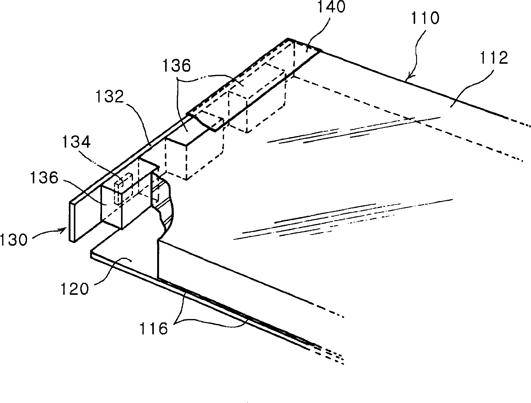
[0044] First, refer to Figure 2 to Figure 7 The light source guiding structure according to the first embodiment of the present invention is explained. In these figures, figure 2 is a perspective view of a light source guiding structure according to a first embodiment of the present invention, image 3 is partially removed from the reflective layer figure 2 A perspective view of the light source guiding structure in, Figure 4 is showing figure 2 Perspective view of the light source and light guide plate in the light source guiding structure in . Figure 5 is figure 2 A plan view of the light source guiding structure in Fig. 6 is a cross-sectional view taken along line 6-6 in Fig. 5, Figure 7 is a cross-sectional view taken along line 7-7 in FIG. 5 .

[0045] Such as Figure 2 to Figure 7As shown in , the light source guiding struc...


PUM


Abstract

The present invention relates to a light source-guide structure having an LED as a light source and a backlight apparatus having the same. The light source-guide structure includes a light guide plate with grooves formed in a peripheral side thereof and a light source having a transparent package fitted into the groove of the light guide plate with an LED chip inside the transparent package. The structure also includes a wiring substrate for seating the LED chip and reflecting the light from the LED chip to the light guide plate and a reflection layer attached on upper surfaces of the light source and the light guide plate. With the light source inserted into the light guide plate, the loss of light is minimized while the horizontal beam angle of light from the LED is increased, minimizing the peripheral area.

Description

[0001] This application claims the benefit of Korean Patent Application No. 2005-60782 filed with the Korean Intellectual Property Office on Jul. 6, 2005, the disclosure of which is hereby incorporated by reference. technical field [0002] The present invention relates to a backlight device having a light emitting diode (LED) as a light source. More particularly, the present invention relates to a light source guiding structure of a backlight device and a backlight device including the light source guiding structure, wherein a light source is located in a light guide plate to minimize loss of light incident from LEDs into the light guide plate, The amount of incident light is increased while increasing the horizontal beam angle of light emitted from the LED, thereby minimizing the peripheral area. Background technique [0003] Since a liquid crystal display (LCD) has no light source of its own, external lighting, usually a bac...

Claims


Application Information

Patent Timeline
IPC IPC(8): G02F1/13357G02F1/1335
CPCG02B6/0021G02B6/0055G02F1/1335
Inventor 金昶煜庐在基洪性在宋怜宰金炳晚
Owner SAMSUNG ELECTRO MECHANICS CO LTD
Why Eureka
Try Eureka