
Drive circuit of low-noise brush-less DC. fan

A DC fan and drive circuit technology, applied in the direction of torque ripple control, etc., can solve the problems of inability to form a trapezoidal drive signal, power consumption, and poor operation efficiency.

Inactive Publication Date: 2007-01-10
ADDA
View PDF0 Cites 7 Cited by
  • Summary
  • Abstract
  • Description
  • Claims
  • Application Information

AI Technical Summary

Problems solved by technology

However, this design still has its negative effects, that is, if the square wave signal is to be changed into a trapezoidal signal, the signal frequency cannot be too high, but the frequency of the oscillation circuit of the above-mentioned drive circuit is about tens of K18-30KHz, which cannot An effective trapezoidal drive signal is formed. Therefore, if this trapezoidal drive signal is to achieve the same speed as the PWM pulse drive signal, its current needs to be increased.
Generally speaking, if the speed of 4000 rpm is to be achieved, the above-mentioned drive circuit only needs about 300 mA of current, while this drive circuit requires at least 350 mA of current, which consumes more power in comparison. The efficiency is also relatively poor
[0010] Judging from the design of the above two drive circuits for pulse modulation and speed control, both have their shortcomings to be improved.

Method used


Image

  • Drive circuit of low-noise brush-less DC. fan
  • Drive circuit of low-noise brush-less DC. fan
  • Drive circuit of low-noise brush-less DC. fan

Examples


Embodiment Construction

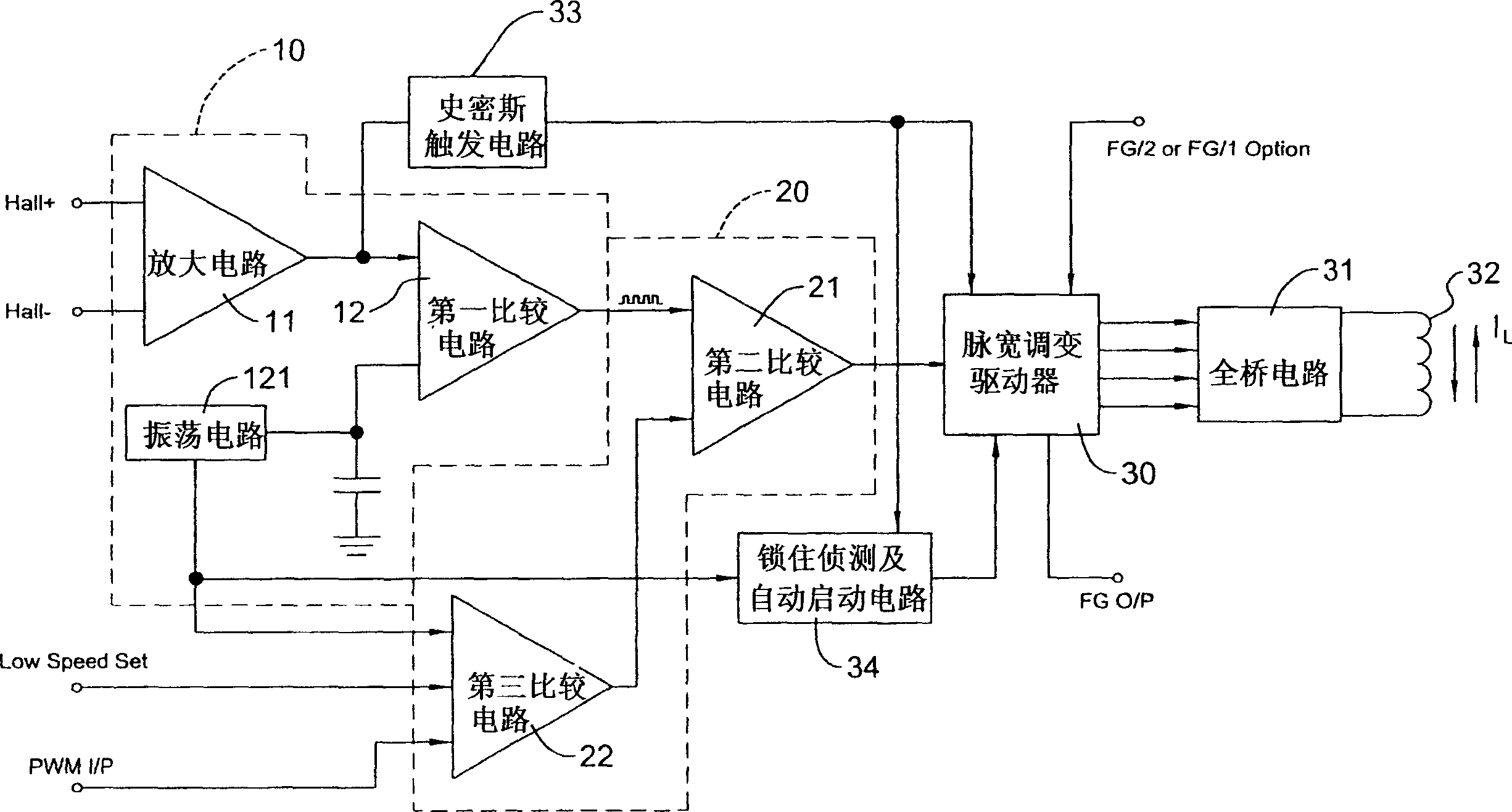
[0047] See first figure 1 As shown, it is a circuit block diagram of a preferred embodiment of the brushless DC motor drive circuit of the present invention, which mainly includes:

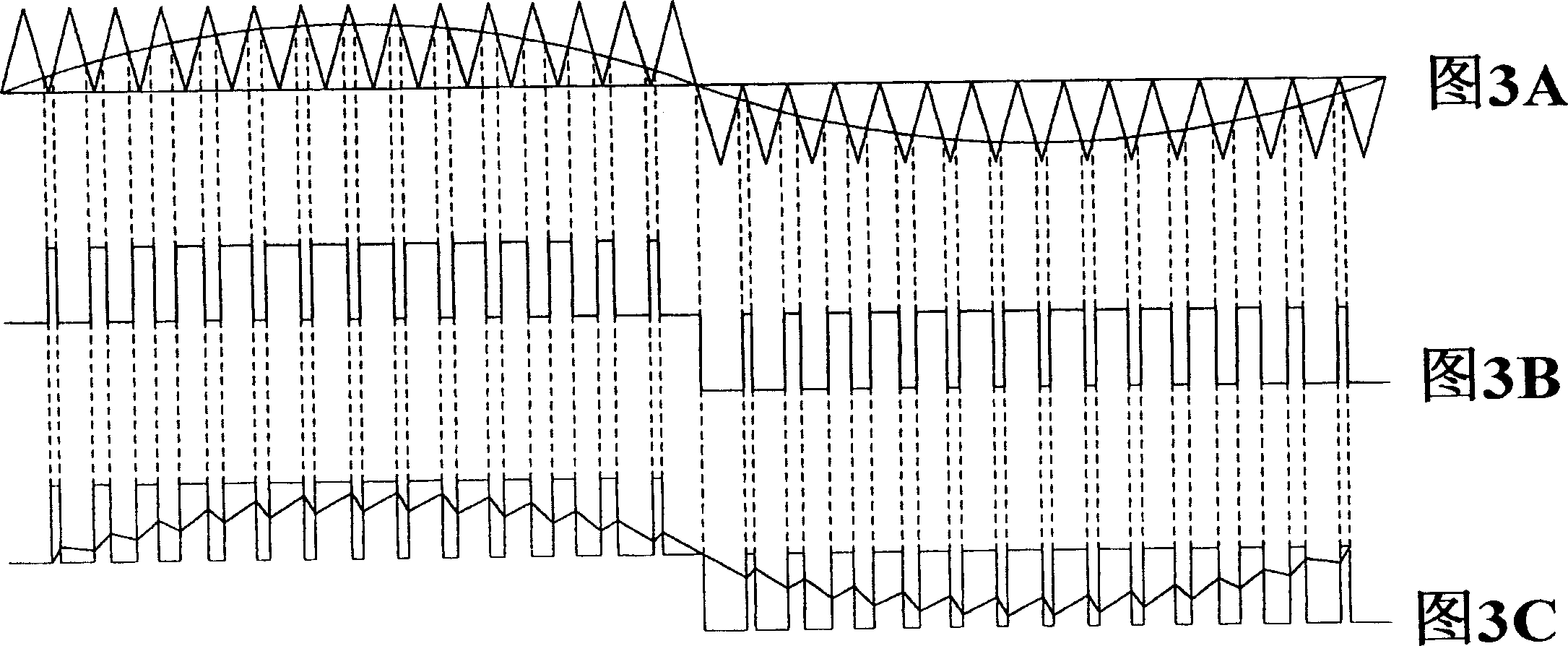
[0048] A Hall pulse width modulation signal generating circuit 10, which is not shown in the figure for the connection of the Hall sensor, converts the Hall sine wave signal Hall+ / Hall- into a pulse width modulation signal, and makes the pulse width modulation signal of the pulse width modulation signal Width modulation with the amplitude of the Hall sine wave signal;

[0049] A rotational speed judging signal generation circuit 20 is connected to the output end of the Hall pulse width modulation signal generation circuit 10 to compare with the external PWM signal PWM I / P for controlling the rotational speed, so as to output pulses containing the rotational speed. Wide modulation signal SPWM;

[0050] A pulse width modulation driver 30, which includes a Hall signal input end, a SPWM signal inpu...


PUM


Abstract

The drive circuit converts Hall harmonic signal to a pulse width modulation signal changed following change of Hall harmonic signal. Comparing the pulse width modulation signal with external rotation control signal generates pulse width modulation signal including rotation control signal. Inputting pulse width modulation signal to pulse width modulation driver outputs pulse width modulation drive signal with changeable pulse width for controlling current direction of single winding for full bridge circuit under certain rotation control signal. The said outputted pulse width modulation drive signal reduces ripple of current signal in winding so as to become smooth signal of current waveform near to harmonic. The invention improves running noise of DC motor effectively.

Description

technical field [0001] The invention relates to a drive circuit for a brushless DC motor fan, in particular to a drive circuit for a brushless DC motor that can effectively improve noise. Background technique [0002] There are two common drive types for brushless DC motors: single-phase full-wave and dual-phase half-wave. At present, in order to make the brushless DC motor have the function of temperature control or easy to adjust the motor speed, the drive IC mainly adopts pulse width modulation driver. Please refer to Figure 4 As shown, it is a current block diagram of a brushless DC motor drive circuit that uses pulse width modulation to control the speed, which includes: [0003] A pulse width modulation driver 50, which includes a Hall signal input terminal, a PWM input terminal, a low speed setting terminal, a frequency generation output terminal and a reset terminal, and its timing signal input terminal is connected to an oscillation circuit 501 About tens of K out...

Claims


Application Information

Patent Timeline
Patent Type & Authority Applications(China)
IPC IPC(8): H02P6/10
Inventor 谢新茂
Owner ADDA
Learn More