Machine-room-less elevator apparatus

A machine room-less elevator and traction machine technology, which is applied to elevators, lifts, transportation and packaging in buildings, etc., can solve the problem of rising product costs and construction costs, damage to the appearance of buildings, and the area and height of the top of the shaft. Increase and other problems, to achieve the effect of low price, reduction of equipment cost, and reduction of construction cost

Inactive Publication Date: 2007-01-10
MITSUBISHI ELECTRIC CORP
View PDF2 Cites 5 Cited by
  • Summary
  • Abstract
  • Description
  • Claims
  • Application Information

AI Technical Summary

Problems solved by technology

[0006] Since the conventional machine-roomless elevator device has the above-mentioned structure, in a large-capacity elevator with a large load capacity, the capacity of the traction machine becomes larger, and the traction machine becomes larger. In this way, the components supporting the traction machine As a result, the top of the hoistway may protrude more than the roof of the building, deteriorating the appearance of the building.
In addition, due to the increase in the size of the traction machine and the increase in the size of the support parts of the traction machine, there is a problem that product costs and construction costs increase

Method used


Image

  • Machine-room-less elevator apparatus
  • Machine-room-less elevator apparatus
  • Machine-room-less elevator apparatus

Examples


Embodiment 1

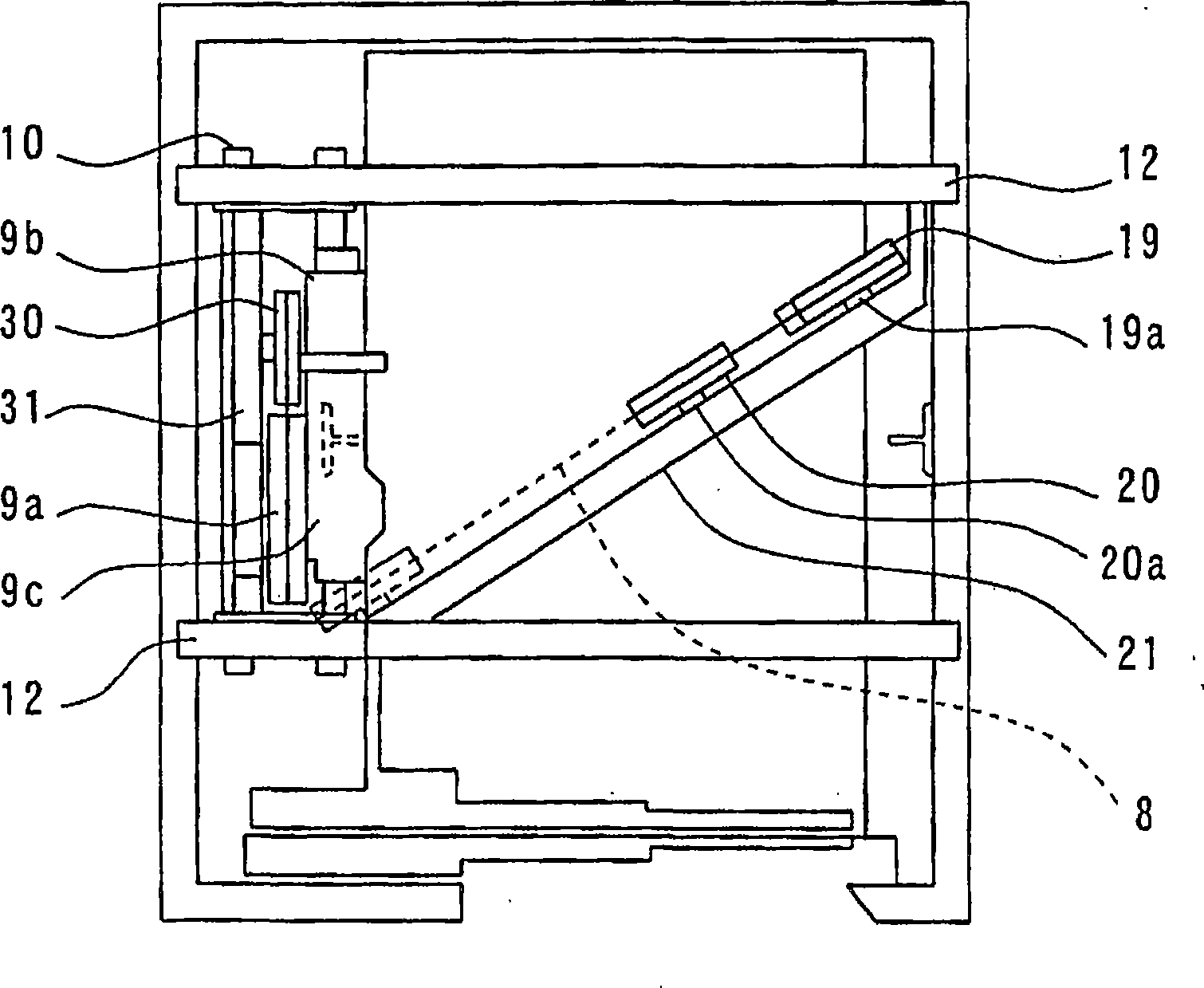
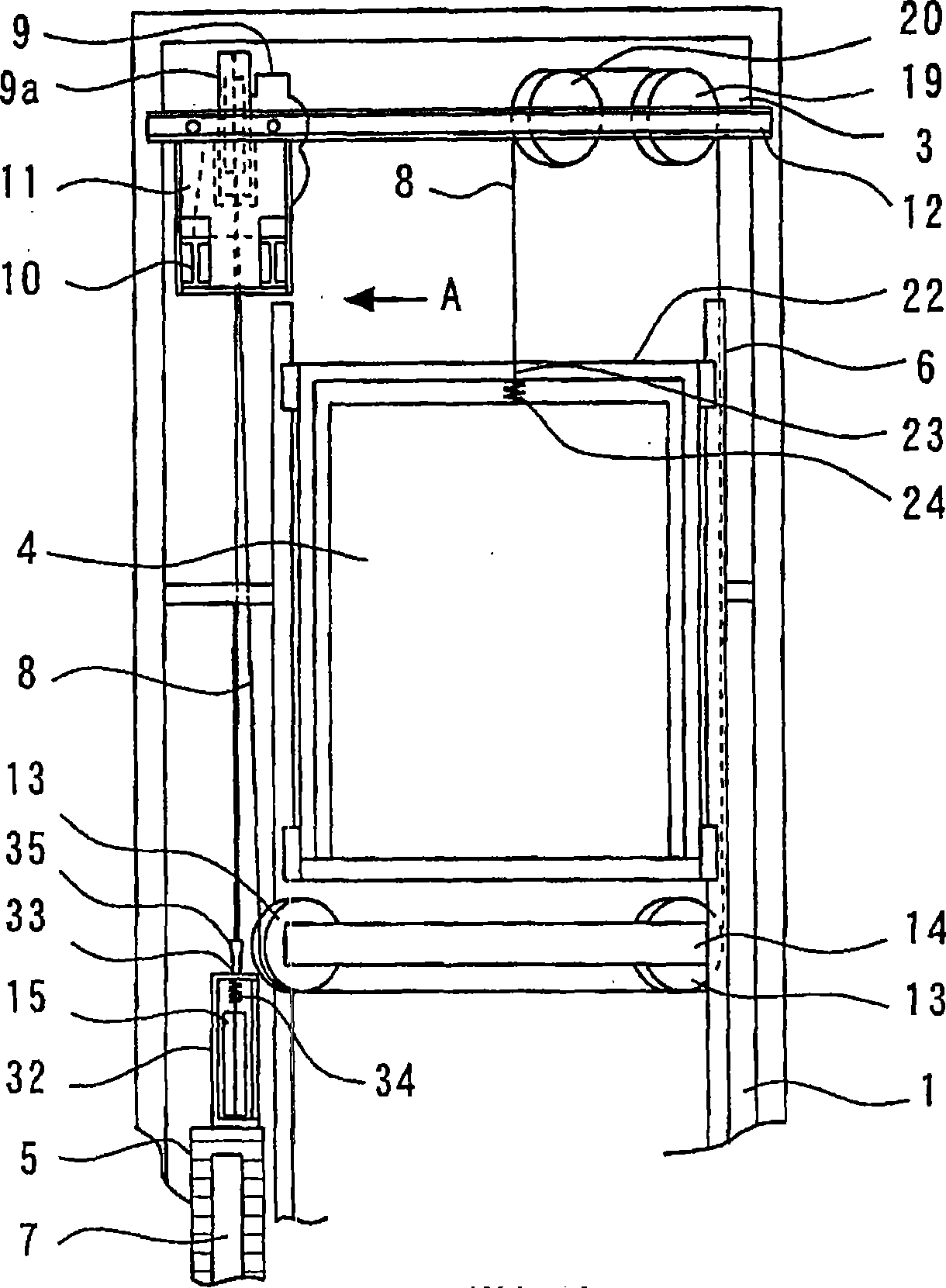
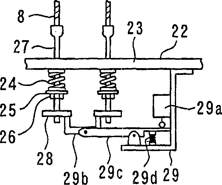
[0029] figure 1 It is a hoistway plan view showing the elevator device in Embodiment 1 of the present invention, figure 2 It is a front view showing the upper part of the hoistway of the elevator device in Embodiment 1 of the present invention, image 3 It is an enlarged view showing the weighing device provided on the car top beam of the elevator apparatus in Embodiment 1 of the present invention.

[0030]In the figure, 1 is the hoistway, 2 is the bottom pit of the hoistway, 3 is the top of the hoistway, 4 is the lift car in the hoistway 1; Heavy, 6 is the guide rail for the car that limits the movement of the car 4 along the horizontal direction, 7 is the guide rail for the counterweight that limits the movement of the counterweight 5 along the horizontal direction, 8 is the rope for suspending the car 4 and the counterweight 5, 9 It is a thin traction machine that drives the car 4 and the counterweight 5 through the rope 8 to make them go up and down. The hoisting mach...

Embodiment 2

[0034] Figure 4 is the slave representing the elevator device in Embodiment 2 of the present invention figure 2 The front view when the counterweight is raised as seen from the direction of arrow A in .

[0035] 36 is provided with two counterweight hanging wheels on the left and right sides of the upper part of the counterweight 5, and 37 is a counterweight rope holding part arranged at the center of the counterweight 5 top.

[0036] That is, the other end side of the rope 8 is such a structure: the rope 8 passes from the sheave 9a of the traction machine 9 through the left and right counterweight suspension pulleys 36 on the upper part of the counterweight 5, and a counterweight reversing sheave 30 on the hoistway top 3. , is arranged on the counterweight rope holding part 37 at the center of the upper part of the counterweight 5, thereby suspending the counterweight 5. Thus, the same 3:1 roping system as in the first embodiment described above is constituted.

Embodiment 3

[0038] Figure 5 is the slave representing the elevator device in Embodiment 3 of the present invention figure 2 The front view when the counterweight is raised as seen from the direction of arrow A in .

[0039] 38 is two counterweight hanging wheels arranged on the left and right sides of the counterweight 5 bottom, and 39 is a counterweight rope holding part arranged at the top center of the counterweight 5 .

[0040] That is, the other end side of the rope 8 is such a structure: the rope 8 passes from the sheave 9a of the traction machine 9 through the left and right counterweight suspension pulleys 39 at the bottom of the counterweight 5, and a counterweight reversing sheave 30 at the hoistway top 3. , is arranged on the counterweight rope holding part 39 at the center of the upper part of the counterweight 5, thereby suspending the counterweight 5. Thus, the same 3:1 roping system as in the first embodiment described above is constituted.

[0041] As described above,...


PUM


Abstract

A machine room-less elevator apparatus which enables to reduce an installation space and whose cost can be reduced. The elevator apparatus has an elevator car (4), a counterweight (5), a guide rail (6) for the car, a guide rail (7) for the counterweight, a rope (8) for suspending the car and the counterweight, a sheave (9a) placed at an elevator shaft top section (3) and over which the rope (8) is passed, a motor (9b) for driving the sheave, and a hoist (9) for lifting and lowering the car and the counterweight. The elevator apparatus further has car sheaves (19, 20) arranged at the elevator shaft top section (3), a car suspension sheave (13) provided under the car (4), a counterweight sheave (30) provided at the elevator shaft top section (3), and a counterweight suspension sheave (15) provided at the counter weight (5). The rope (8) is connected at one end to a position near the center of the upper part of the car, passed over a hoist sheave (9a) after it is passed over the car sheaves (19, 20) and the car suspension sheave (13), and suspended via the counterweight suspension sheave (15) and the counterweight sheave (30). The other end is connected to a position near the center of the upper part of the counterweight (5).

Description

technical field [0001] The invention relates to a rope winding system for a large-capacity machine room-less elevator device with a large load capacity. Background technique [0002] Figure 6 It is a hoistway plan showing the existing 2:1 roping system machine room-less elevator installation, Figure 7 It is a front view which shows the said hoistway. In the figure, 1 is the hoistway, 2 is the pit of the hoistway, 3 is the top of the hoistway, 4 is the lift car in the hoistway 1, and 5 is the opposite direction to the car 4 in the hoistway 1. Heavy, 6 is the guide rail for the car that limits the movement of the car 4 along the horizontal direction, 7 is the guide rail for the counterweight that limits the movement of the counterweight 5 along the horizontal direction, 8 is the rope for suspending the car 4 and the counterweight 5, 9 It is a thin traction machine that drives the car 4 and the counterweight 5 through the rope 8 to raise and lower them. The hoisting machin...

Claims


Application Information

Patent Timeline
Patent Type & Authority Applications(China)
IPC IPC(8): B66B7/06
CPCB66B1/3484B66B11/0045B66B11/008
Inventor 滨口修喜
Owner MITSUBISHI ELECTRIC CORP
Why Eureka
Try Eureka