Vacuum cleaner

A vacuum cleaner and electric technology, which is applied in the installation of vacuum cleaners, electrical equipment, and motor fan components. Effect of input power

Inactive Publication Date: 2007-01-17
PANASONIC CORP
View PDF1 Cites 6 Cited by
  • Summary
  • Abstract
  • Description
  • Claims
  • Application Information

AI Technical Summary

Problems solved by technology

However, if the motor-driven fan 1 is driven by the control method described in the above-mentioned reference that not only satisfies the high-order harmonic current but also can change the input, affected by t

Method used


Image

  • Vacuum cleaner
  • Vacuum cleaner
  • Vacuum cleaner

Examples


Embodiment 1

[0044] first use Figure 1 ~ Figure 3 The first embodiment of the present invention will be described. Wherein, for the same components as those in the above prior art, only the same symbols are marked below, and repeated description thereof will be omitted.

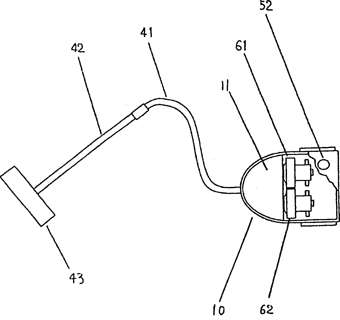
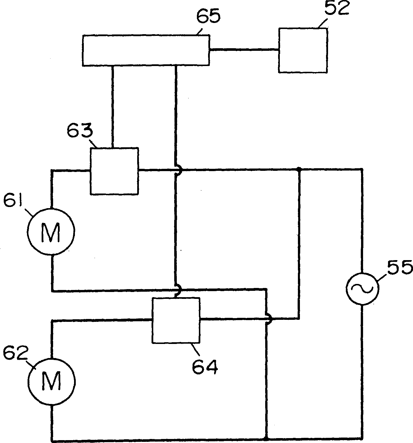
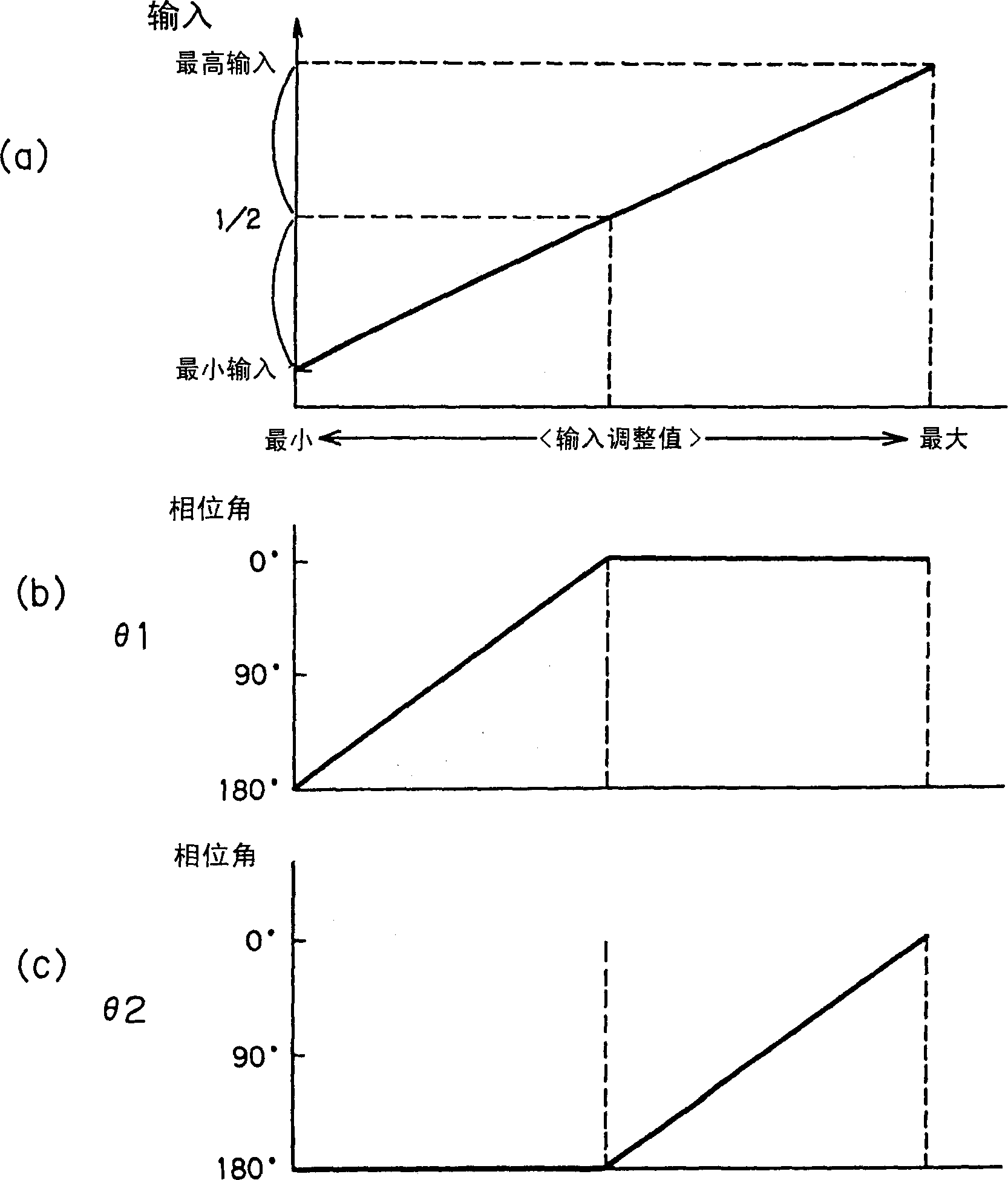
[0045] figure 1 To show the oblique view of the electric vacuum cleaner of the present embodiment, figure 2 Its circuit block diagram, image 3 A graph of the relationship between the input adjustment value and the control state of the electric fan.

[0046] Such as figure 1 As shown in , the electric vacuum cleaner 10 is provided with a first electric blower 61 and a second electric blower 62 . The total value of the maximum power of the first electric fan 61 and the second electric fan 62 is about 1600W or higher, that is, the maximum power consumption of the electric vacuum cleaner 10 is more than 1600W. The suction ports of the electric fans communicate with the dust collecting chamber 11 in the electric vac...

Embodiment 2

[0050] Use below Figure 4 A second embodiment of the present invention will be described. Wherein, for the same components as those in the prior art, only the same symbols are attached here, and their detailed descriptions are omitted.

[0051] Figure 4 It is a relationship diagram between the input adjustment value of the electric vacuum cleaner and the control state of the electric fan in this embodiment.

[0052] The input range in which the electric vacuum cleaner can work is the range between the lowest input value and the highest input value. Before vacuuming, the user first sets the input to the desired value, and then makes the vacuum cleaner perform the vacuuming operation. When operating the electric vacuum cleaner, desired power supply power is applied to both the first electric blower 61 and the second electric blower 62 . Assuming that the energized phase angle of the first electric fan 61 is controlled by the first control device 63 to be θ1, and the energi...

Embodiment 3

[0056] Use below Figure 5 Now, the third embodiment of the present invention will be described. Wherein, for the same components as those in the existing device, only the same symbols are assigned below, and repeated description thereof will be omitted.

[0057] Such as Figure 5 As shown in , the electric vacuum cleaner 10' is provided with a first electric blower 61 and a second electric blower 62, the suction port of the first electric blower 61 communicates with the dust collection chamber 11 in the electric vacuum cleaner 10', and the second electric blower 62 is provided on the downstream side of the first electric fan 61 . The first electric blower 61 and the second electric blower 62 are controlled according to the control method in the above-mentioned embodiment 1 or embodiment 2.

[0058] With the above-mentioned structure, after the electric fan is arranged in series in the electric vacuum cleaner, the vacuum pressure of the electric fan can be increased when tw...


PUM


Abstract

The invention provided a vacuum cleaner for which the raise in inputs is possible, and also, which can realize an input control by a phase control in a broad range. The vacuum cleaner is equipped with a first control means (63) which controls a first electric blower (61), a second control means (64) which controls a second electric blower (62), an input adjusting means (52), a commercial power source (55), and a main control means 65 which controls the first control means 63 and the second control means (65) in response to a signal from the input adjusting means. The total of the maximum power consumption of the first and second electric blowers is approximately 1,600W or higher. At the same time, the vacuum cleaner is constituted in such a manner that the first electric blower is connected with the commercial power source through the first control means, and the second electric blower is connected with the commercial power source through the second control means 64 respectively in parallel. The electric vacuum cleaner achieves the raise in input, suppresses the generation of a high harmonic electric current by the phase control, and allows the input control over the whole range of the maximum input and lower.

Description

technical field [0001] The present invention relates to an electric vacuum cleaner with high input power (high maximum power consumption) and the user can adjust the input power arbitrarily according to the situation, so it is very convenient to use. This kind of vacuum cleaner is very popular especially in Europe, Asia, Middle East and other regions. welcome. Background technique [0002] first use Figure 9 ~ Figure 12 The general configuration of the above-mentioned conventional electric vacuum cleaner will be described. [0003] Such as Figure 9 , Figure 10 As shown in , the electric vacuum cleaner 30 is provided with: a rotary or sliding input adjustment device 52 for the user to adjust the input power of the electric vacuum cleaner 30 according to the situation; a main control device 37 for controlling; and a triac (hereinafter simply referred to as “triac”) 36 for phase controlling the electric fan 1 . Electric blower 1 is made up of motor and fan part. [0004...

Claims


Application Information

Patent Timeline
IPC IPC(8): A47L5/12A47L9/28
CPCA47L5/22A47L9/2842A47L9/22
Inventor 村田吉隆西村刚秀熊哲平
Owner PANASONIC CORP
Why Eureka
Try Eureka