Accuracy correction for light-curing fast formation

A technology of molding process and calibration method, which is applied in the field of scanner precision calibration of light curing rapid prototyping process, can solve the problems of difficult, difficult and inaccurate distance measurement, and achieve the effect of high calibration accuracy and fast calibration

Inactive Publication Date: 2007-01-17
NANJING HONNY 3 DIMENSIONAL TECH
View PDF0 Cites 16 Cited by
  • Summary
  • Abstract
  • Description
  • Claims
  • Application Information

AI Technical Summary

Problems solved by technology

[0005] In actual production, it is very difficult to measure the distance from the center point of the scanner to the center point of the molding surface (resin surface). In addition, the position of the molding surface (resin surface) is related to the amount of resin in the resin tank and the resin temperature
Therefore,

Method used


Image

  • Accuracy correction for light-curing fast formation
  • Accuracy correction for light-curing fast formation
  • Accuracy correction for light-curing fast formation

Examples


Embodiment Construction
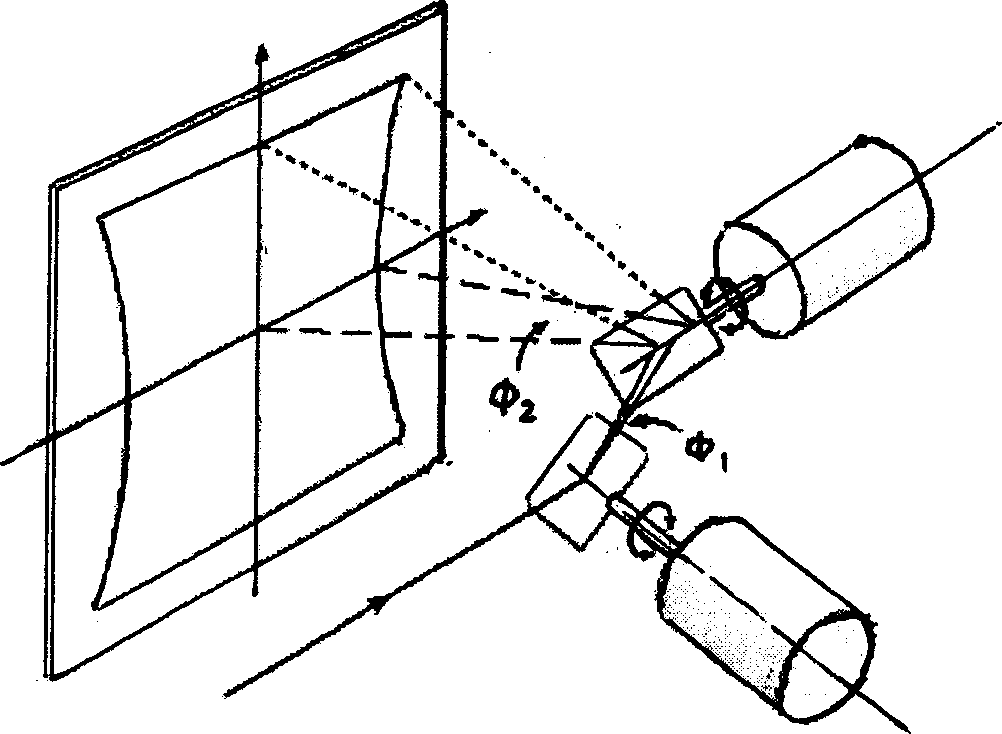
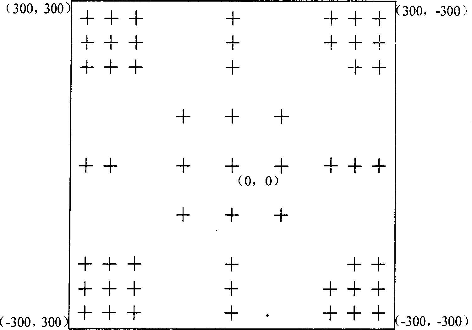
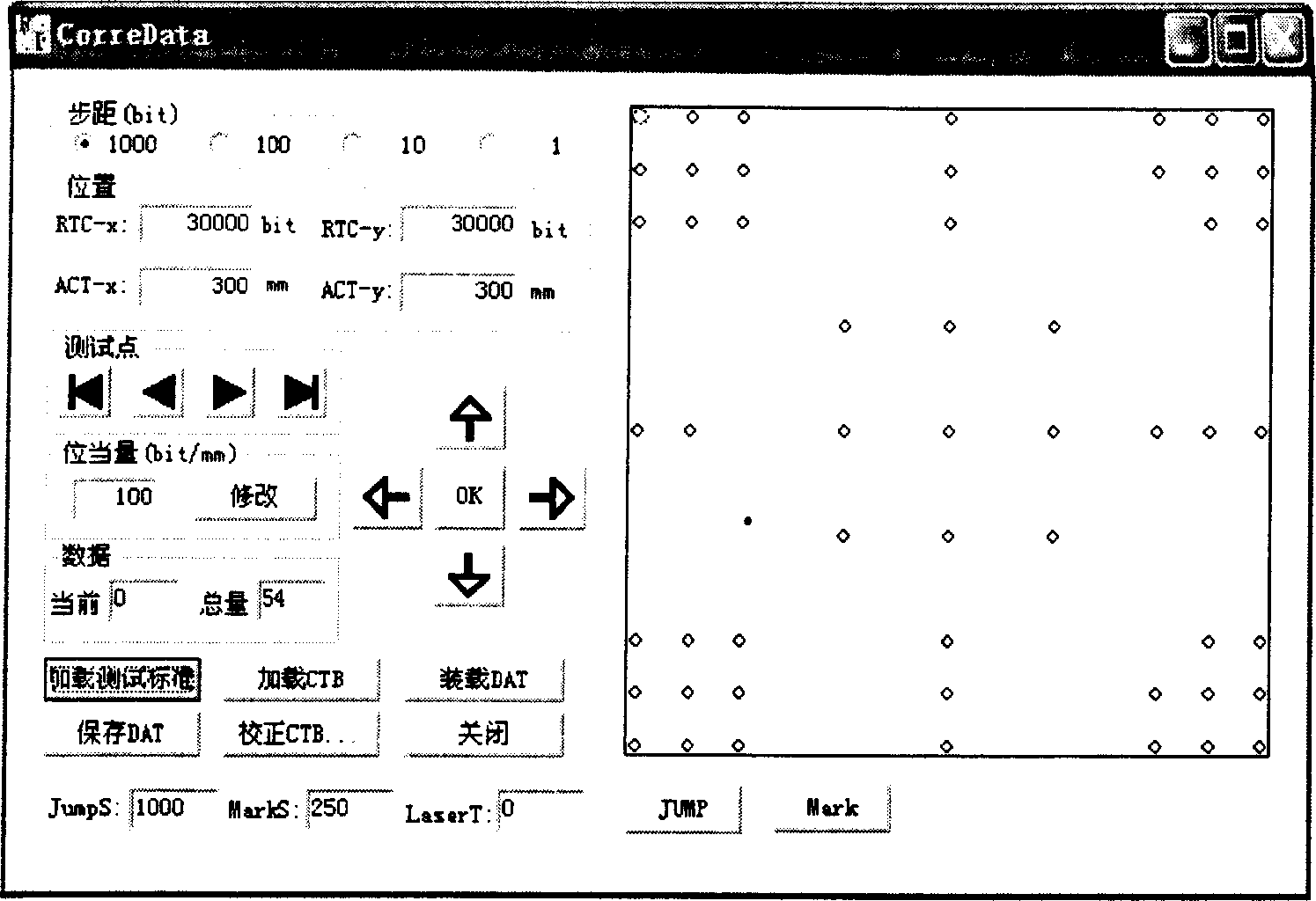
[0017] The basic idea of ​​the accuracy correction method used in the light-curing rapid prototyping process of the present invention is to use a calibration plate, and the calibration points are processed by high-precision numerical control machine tools on the entire surface of the calibration plate. There are 54 scale points for the molding machine, and 33 scale points for the 350×350 light-curing rapid prototyping machine, and the accuracy is guaranteed to be within ±5 μm. Through detection methods such as a level meter, the calibration plate is coincident with the molding plane (resin surface), and the computer controls the scanner of the light-curing rapid prototyping machine to control the laser spot as close as possible to the scale point point by point, and record the correction value of each correction point. Generate an actual calibration file. The scanner can compensate and correct each scanning point according to the new calibration file during operation.

[0018...


PUM


Abstract

A precision correcting method for the fast shaping technology by optical solidifying includes such steps as arranging a calibrating plate on a lattice plate with a standard distance from the edge of resin bath and coinciding with the shaping plane of fast photosolidifying shaping machine, and controlling a scanner by computer to correct each dots one by one. Said computer has a movement control card and a correcting program for creating a correcting file.

Description

technical field [0001] The invention belongs to a method and a device in the technical field of rapid prototyping, in particular to a method for correcting the accuracy of a scanner used in a photocuring rapid prototyping process. Background technique [0002] Light-curing rapid prototyping uses photosensitive resin as a raw material, and the computer controls the scanning trajectory of the ultraviolet laser to cure the resin. First, the tank is filled with liquid photosensitive resin, and the ultraviolet laser beam emitted by the laser is scanned point by point on the surface of the photosensitive resin according to the layered section information of the part under the control of the deflection system. The thin layer of resin in the scanned area is irradiated by ultraviolet light. Instead, photopolymerization occurs, curing to form a thin layer of the part. After that, the workbench moves down by a thin layer thickness, so that a new layer of liquid...

Claims


Application Information

Patent Timeline
IPC IPC(8): B29C67/00
Inventor 王伊卿卢秉恒周宏志赵万华李涤尘丁玉成
Owner NANJING HONNY 3 DIMENSIONAL TECH
Why Eureka
Try Eureka