Production of carbon nano-tube array

A carbon nanotube array and fabrication method technology, which is applied in the field of directional controllable carbon nanotube array fabrication, can solve the problems of increasing the complexity of device design and difficult to achieve control, and achieves the effects of enriching design diversity and simple process

Active Publication Date: 2007-01-17
TSINGHUA UNIV +1
View PDF0 Cites 9 Cited by
  • Summary
  • Abstract
  • Description
  • Claims
  • Application Information

AI Technical Summary

Problems solved by technology

[0007] However, in the above methods, the method of controlling the growth direction of carbon nanotubes with an electric field will increase the complexity of device design, and due to the wide-area nature of the electric field itself, it is difficult to control multiple local growth directions.

Method used


Image

  • Production of carbon nano-tube array
  • Production of carbon nano-tube array
  • Production of carbon nano-tube array

Examples


Embodiment Construction

[0038] The embodiments of the present invention will be further described in detail below in conjunction with the accompanying drawings.

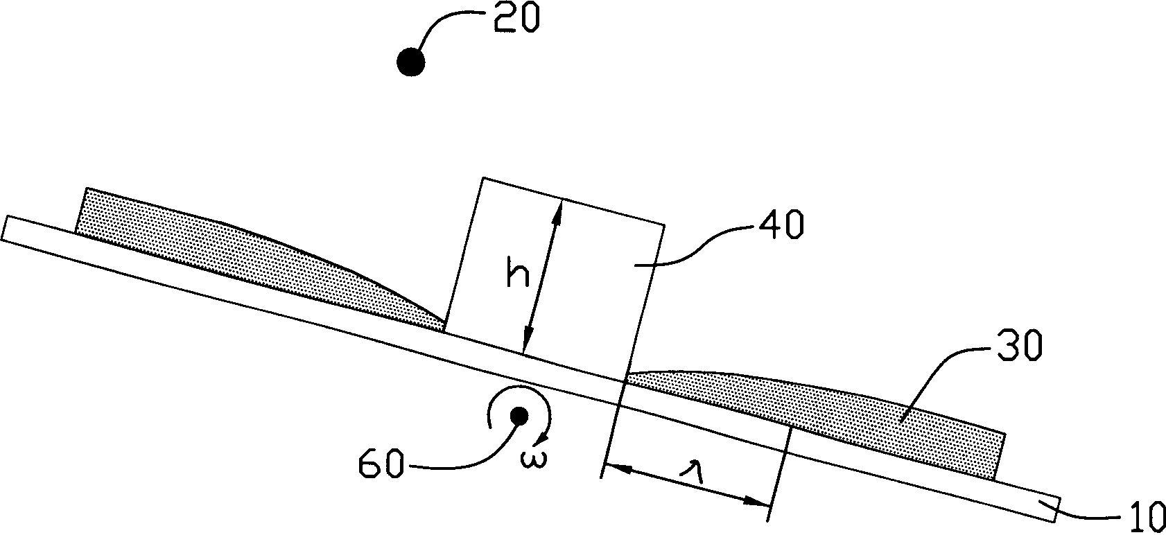
[0039] see figure 1 , the carbon nanotube array manufacturing method provided by the first embodiment of the present invention includes the following steps:

[0040] (1) Provide a base 10 on which a shielding layer 40 with a certain thickness is formed. The substrate 10 can be a silicon wafer, a glass wafer, a metal wafer, etc.; a silicon wafer is used in this embodiment. The shielding layer 40 has a vertical shielding edge with a certain height, which is the thickness of the shielding layer 40, so that the shielding layer 40 can shield the part of the catalyst evaporated from the point evaporation source 20, so that the thickness of the obtained catalyst film 30 has a certain thickness range. The gradient of the inner gradient. The shielding layer 40 can be made of thick film photoresist, metal or metal oxide, metal nitride attached to ...


PUM


Abstract

Production of carbon nanometer-tube array is carried out by providing basis with shielding layer, providing catalyst evaporator source, rotating basis along rotating axis, forming thickened-gradient catalyst thin-film on basis, eliminating shielding layer, defining a catalyst regional block on catalyst thin-film, thinning the thickness of catalyst regional block from the first end to the second end while reaching the optimum thickness in the range of the first end and the second end, treating the catalyst regional block into catalyst granular array, inducing into carbon source gas, growing carbon nanometer-tube array by CVD method and bending the carbon nanometer-tube array in the optimum thickness direction reversely. It can reach local multi-direction growth of carbon nanometer-tube array.

Description

【Technical field】 [0001] The invention relates to a method for manufacturing a carbon nanotube array, in particular to a method for manufacturing a direction-controllable carbon nanotube array. 【Background technique】 [0002] Due to the unique electrical properties of carbon nanotubes, their applications in the fields of nano-integrated circuits and single-molecule devices have immeasurable prospects. At present, people have been able to manufacture a small amount of carbon nanotube-based field effect transistors, NOR gates and other devices in the laboratory, and study its properties. But for large-scale preparation and practical application, we must resort to bottom-up (Bottom Up) preparation process. [0003] The bottom-up preparation process requires the necessary control over the growth position, direction, scale, and even the helicity of carbon nanotubes, and directly grows the required device structure through a small number of economical steps. Fan Shoushan et al. ...

Claims


Application Information

Patent Timeline
IPC IPC(8): C01B31/02
CPCC01B2202/08B82Y40/00C01B31/0233B82Y30/00Y10S977/89Y10S977/843Y10S977/84C01B32/162
Inventor 刘亮范守善
Owner TSINGHUA UNIV
Why Eureka
Try Eureka