Panel machining method and apparatus

A processing method and surface processing technology, applied in the direction of metal processing equipment, metal processing machinery parts, sustainable manufacturing/processing, etc., can solve the problems that the rigidity of the panel to be processed cannot be reliably guaranteed, and high-precision processing cannot be used

Inactive Publication Date: 2007-01-17
迪菲厄工业公司 +1
View PDF1 Cites 24 Cited by
  • Summary
  • Abstract
  • Description
  • Claims
  • Application Information

AI Technical Summary

Problems solved by technology

[0008] Obviously, while this equipment can actually be used efficiently for removing material from non-developable twisted or complex-sh

Method used


Image

  • Panel machining method and apparatus
  • Panel machining method and apparatus
  • Panel machining method and apparatus

Examples


Embodiment Construction

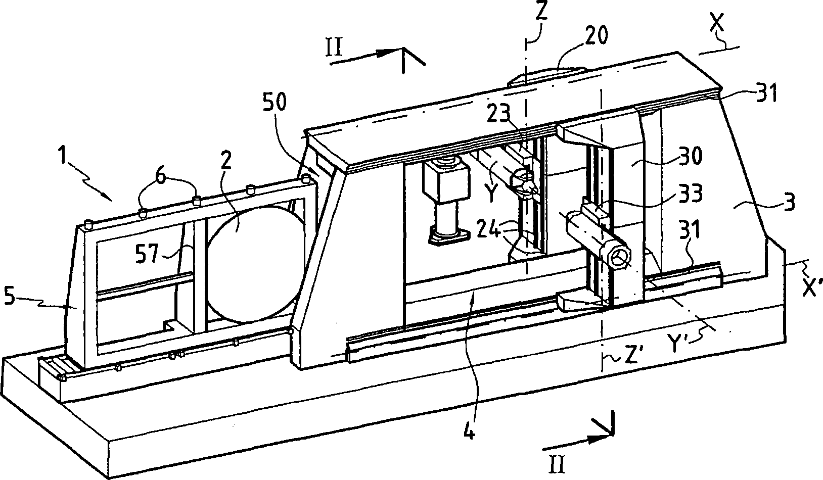
[0078] figure 1 The processing apparatus of the present invention is shown, generally referenced 1 and capable of processing panels 2, often of complex and non-developable overall shapes, eg convex or concave or partially convex and partially concave.

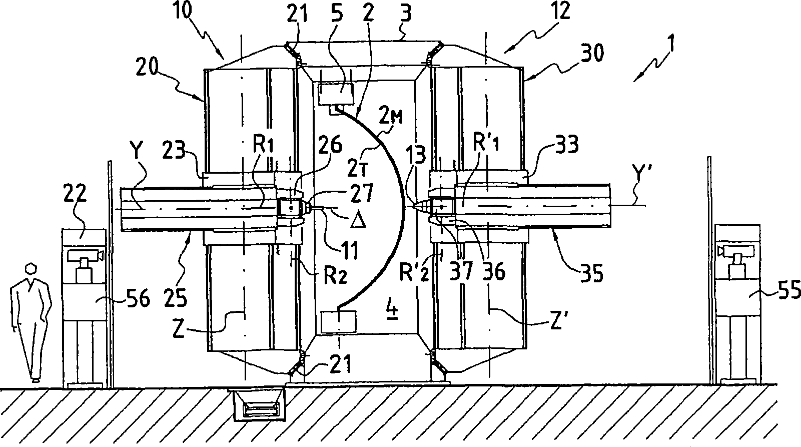
[0079] In order to carry out the processing method, the plant 1 comprises a base frame 3 which, according to the embodiment shown, is formed as some form of a substantially vertical colonnade, the interior of which defines a window 4 in which the panels to be processed can be positioned inside the window and held there by the support means 5 . According to the embodiment shown, this support means 5 is in the form of a movable frame, which can be fixed in the window 4 of the base frame 3 by means of locking means 6 provided in any suitable form.

[0080] According to an essential feature of the invention, the machining device 1 also comprises a moving device 10 for at least one tool, in the example shown, exactly a machining to...


PUM


Abstract

The invention relates to a method for machining a panel (2). According to said method, at least one machining tool (11) is arranged in a working area (50) of a so-called machining surface (2T) of the panel (2); at least one holding element (13) is arranged in a support area (52) located on a so-called holding surface (2M) of the panel (2), opposing the machining surface (2T), and on the opposite side, in relation to the panel (2), to the working area (50); and the operating machining tool (11) and the holding element (13) are displaced on the panel in a co-ordinated manner, according to a movement presenting at least one component tangentially to the surface of the panel, in such a way as to maintain the opposition of the support area (52) and the working area (50) during the displacement of the tool, in order to machine at least part of the machining surface. The invention also relates to a device for implementing said method.

Description

technical field [0001] The present invention relates to apparatus and methods for processing preformed blanks or panels, such as those used in the manufacture of aircraft cabins or fuselages. Background technique [0002] In the aforementioned fields, we are familiar with the process of machining preformed panels into non-deployable shapes by electro-erosion. This processing involves masking off areas not to be treated and then immersing (the panel) in an electrolyte solution. Thus, this method allows efficient local machining of panels that are generally non-developable in shape. However, this method has two major disadvantages. [0003] Firstly, machining by galvanic corrosion requires a significant source of emissions that needs to be dealt with, so that the panels first have to be cleaned after machining by removing the mask and then circulated to flush out the cleaning solution and the different electrolytic solutions used. [0004] Another disadvantage of machining ...

Claims


Application Information

Patent Timeline
IPC IPC(8): B23Q1/01B23Q1/62B23Q1/48B21J15/10B23Q1/54B23Q1/76B64F5/00
CPCB23Q1/626B23Q1/4857B23Q1/488B23Q1/5412Y02T50/90B64F5/0009B23Q1/766B64F5/10Y02P70/50
Inventor R·潘奇祖克P-Y·富瓦萨克
Owner 迪菲厄工业公司
Why Eureka
Try Eureka