Method for reducing industrial furnace shell heat loss by mounting heat insulation box on furnace outer shell

A thermal insulation box and industrial furnace technology, applied in the field of heat treatment, can solve the problems of high cost, large heat loss, difficult production and installation, etc., and achieve the effects of simple manufacturing process, improved thermal insulation performance, and reduced heat dissipation loss

Inactive Publication Date: 2007-01-24
SHANGHAI JIAO TONG UNIV
View PDF1 Cites 6 Cited by
  • Summary
  • Abstract
  • Description
  • Claims
  • Application Information

AI Technical Summary

Problems solved by technology

In order to save energy, protect the environment, and effectively utilize existing resources, it is necessary to carry out energy-saving transformation of industrial furnaces. Generally, industrial furnaces are only covered with a layer of steel plates outside the furnace lining. This layer of steel plates not only protects the furnace lining, but also strengthens the furnace lining. The effect of sealing to reduce the heat loss of the furnace, but the surface temperature of the furnace shell is still high, the heat loss is relatively large, and the working environment is deteriorated at the same time. If only thickening the furnace lining to reduce heat loss will increase the heat storage of the furnace lining Loss, add one or more layers of shell outside the industrial furnace, set one or more air gaps, this structure does not increase the thickness of the furnace lining but can reduce heat loss, and can achieve good energy-saving effects
[0003] After searching the existing technical literature, it is found that the patent application number is 99124184.3, and the name is: method for reducing heat loss of industrial furnace shell. This technology adopts the method of double-layer furnace shell structure, and a layer of thin steel plate is installed outside the furnace shell or aluminum plate, the enclosed air layer formed increases the thermal resistance
This technology has the following disadvantages: the energy-saving method of industrial furnaces with a double-layer furnace shell structure made of thin steel plates or aluminum plates, because the gas parallel to the wall in the compartment can still flow freely, affecting the heat insulation effect; the heat conduction of steel plates and aluminum plates High efficiency, large heat loss; difficult to manufacture and install, and relatively high cost

Method used


Image

  • Method for reducing industrial furnace shell heat loss by mounting heat insulation box on furnace outer shell
  • Method for reducing industrial furnace shell heat loss by mounting heat insulation box on furnace outer shell

Examples


Embodiment 1

[0021] The maximum working temperature of RJX-50 high-temperature box-type resistance furnace: 1300°C Overall dimensions: 1890mm×2880mm×2050mm.

[0022] 1. Install 80 double-layer insulation boxes with a plane size of 226mm×230mm×20mm on both sides of the furnace. The thickness of the side wall and sealing surface of the box is 1mm. Each box is put into two layers of ribs, and the height of each layer of ribs is 8.5 mm, two longitudinal ribs with a length of 228mm, and two transverse ribs with a length of 224mm. The first step of installation is to put a piece of aluminum foil with an area of ​​224mm×228mm into the box, the second step is to put a layer of ribs, the third step is to put an aluminum plate with a thickness of 1mm, and the fourth step is to put a layer of ribs, and then Fix the box on the furnace shell with screws at the four corners of each box. 36 same heat preservation boxes are installed on the furnace shell of the furnace rear wall.

[0023] 2. The top sur...

Embodiment 2

[0025] The maximum operating temperature of RJX-75 medium-temperature box-type trolley resistance furnace: 950°C Furnace wall size: 2500×1735×1500mm.

[0026] 1. Install 70 insulation boxes with a plane size of 452mm×230mm×50mm on both sides of the furnace wall. The thickness of the side wall and the sealing surface of the box is 1mm. Each box is put into a second layer of ribs, and the height of the ribs is 23.5mm. There are four longitudinal ribs with a length of 228mm, and two transverse ribs with a length of 450mm. The first step of installation is to put a piece of aluminum foil with an area of ​​450mm×228mm into the box, the second step is to put a layer of ribs, the third step is to put an aluminum plate with a thickness of 1mm, and the fourth step is to put a layer of ribs, and then Fix the box on the furnace shell with screws at the four corners of each box. The rear wall of the furnace (except for the protective cover at the leading end of the electric heater) is eq...

Embodiment 3

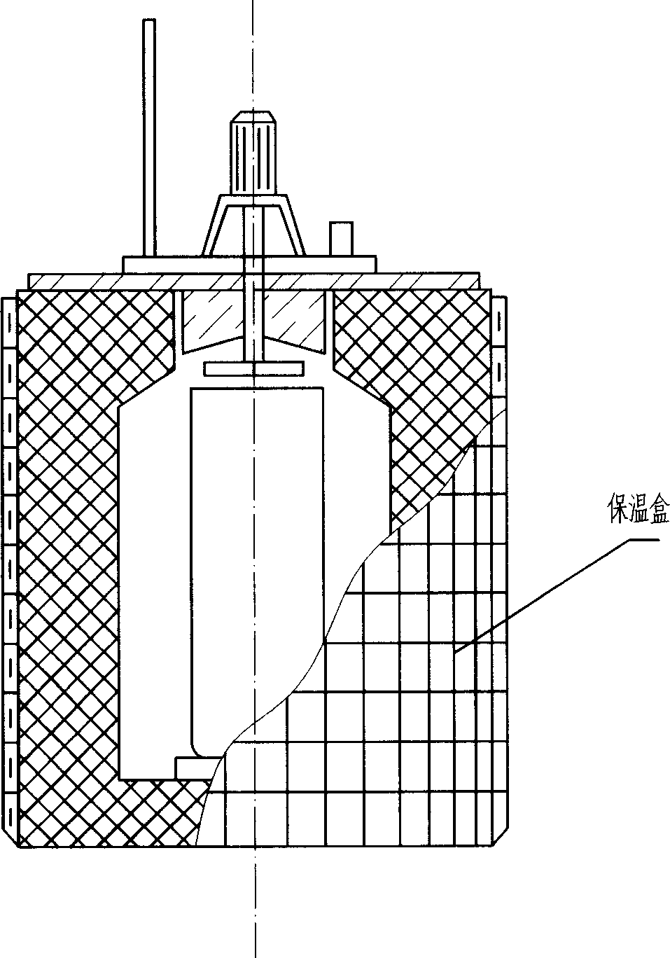
[0029] RJJ-105 pit type gas carburizing furnace, such as figure 1 shown. Maximum operating temperature: 950°C Dimensions: Φ1870×3050mm.

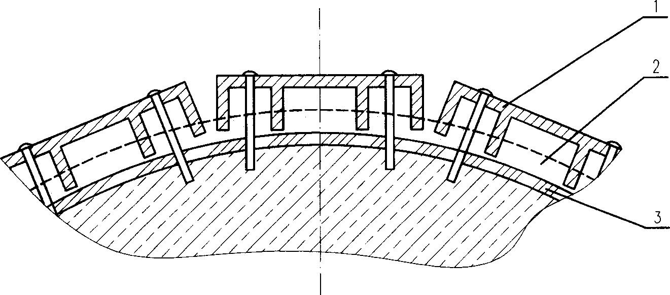
[0030] Install 400 insulation boxes 1 with a plane size of 65×460×10 on the furnace wall (except for the protective cover at the lead end of the electric heater). The thickness of the side wall and sealing surface of the box is 1mm. Each box is put into a layer of ribs. The height of the ribs is 8mm. There is 1 longitudinal rib with a length of 228mm and 6 transverse ribs with a length of 63mm. During installation, the first step is to paint a layer of silica sol evenly on the furnace wall gradually, and then lay a layer of 10mm slag wool blanket. The second step is to put a piece of aluminum foil with an area of ​​228mm×63mm into the box. , the transverse ribs are put into the box, and the fourth step is to fix the four corners of each insulation box on the furnace shell 3 covered with slag cotton blanket 2, such as figure 2 shown.

[...


PUM


Abstract

The method for reducing heat loss from industrial furnace shell by installing heatproof box on furnace shell includes following steps: (1) prefabricating heatproof box on industrial furnace shell; (2) partitioning space inside box by inserting longitudinal ribs and traverse ribs perpendicular to sealing surface inside box in order to reduce gas streaming inside box; (3) using thin plate between two layers of rib to partition box; (4) using fire-resistant heat insulation material to partition off furnace shell from the box; (5) being placed at inner side of sealing surface of the box or between furnace shell and the box, aluminum foil reflects quantity of heat radiated from furnace shell so as to raise insulating property. The invention reduces heat loss caused by convective heat exchange, reflects back quantity of heat radiated from furnace shell so that the invention is an effective measure for saving energy.

Description

technical field [0001] The invention relates to a method in the technical field of heat treatment, in particular to a method for installing a heat preservation box on a furnace shell to reduce heat loss of an industrial furnace shell. Background technique [0002] Industrial furnaces are widely used in metallurgy, casting, heat treatment and forging industries, and their energy consumption accounts for about 80% of thermal processing factories. Therefore, improving the thermal efficiency of industrial furnaces, reducing energy consumption, and prolonging the life of industrial furnaces are one of the key points of industrial furnace research. one. In order to save energy, protect the environment, and effectively utilize existing resources, it is necessary to carry out energy-saving transformation of industrial furnaces. Generally, industrial furnaces are only covered with a layer of steel plates outside the furnace lining. This layer of steel plates not only protects the fur...

Claims


Application Information

Patent Timeline
IPC IPC(8): F27D1/00
Inventor 潘健生徐兴宝顾剑锋陈乃录胡明娟
Owner SHANGHAI JIAO TONG UNIV
Why Eureka
Try Eureka