
Multiple level changing method and its used multiple level circuit

A multi-level and level technology, applied in the direction of irreversible DC power input conversion to AC power output, to achieve high efficiency, reduce electromagnetic interference problems, and good PWM modulation effects

Inactive Publication Date: 2007-01-24
WUHAN UNIV
View PDF0 Cites 10 Cited by
  • Summary
  • Abstract
  • Description
  • Claims
  • Application Information

AI Technical Summary

Problems solved by technology

However, the existing multilevel converter (Multilevel Converter) method can only reduce the related electromagnetic interference problems to a certain extent.

Method used


Image

  • Multiple level changing method and its used multiple level circuit
  • Multiple level changing method and its used multiple level circuit
  • Multiple level changing method and its used multiple level circuit

Examples


Embodiment Construction

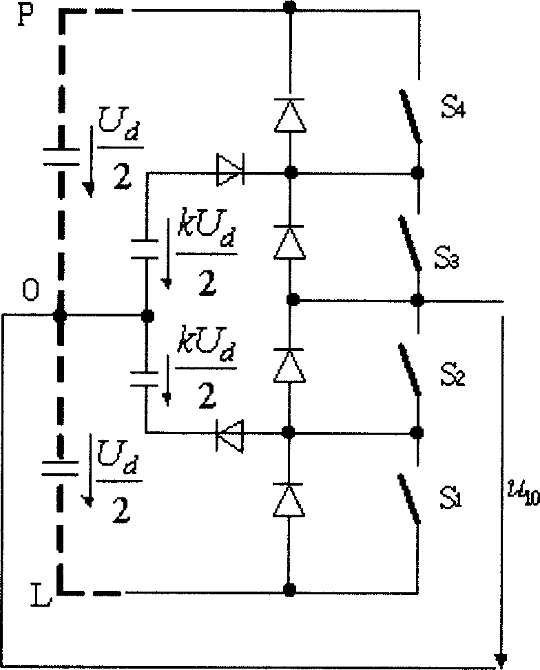
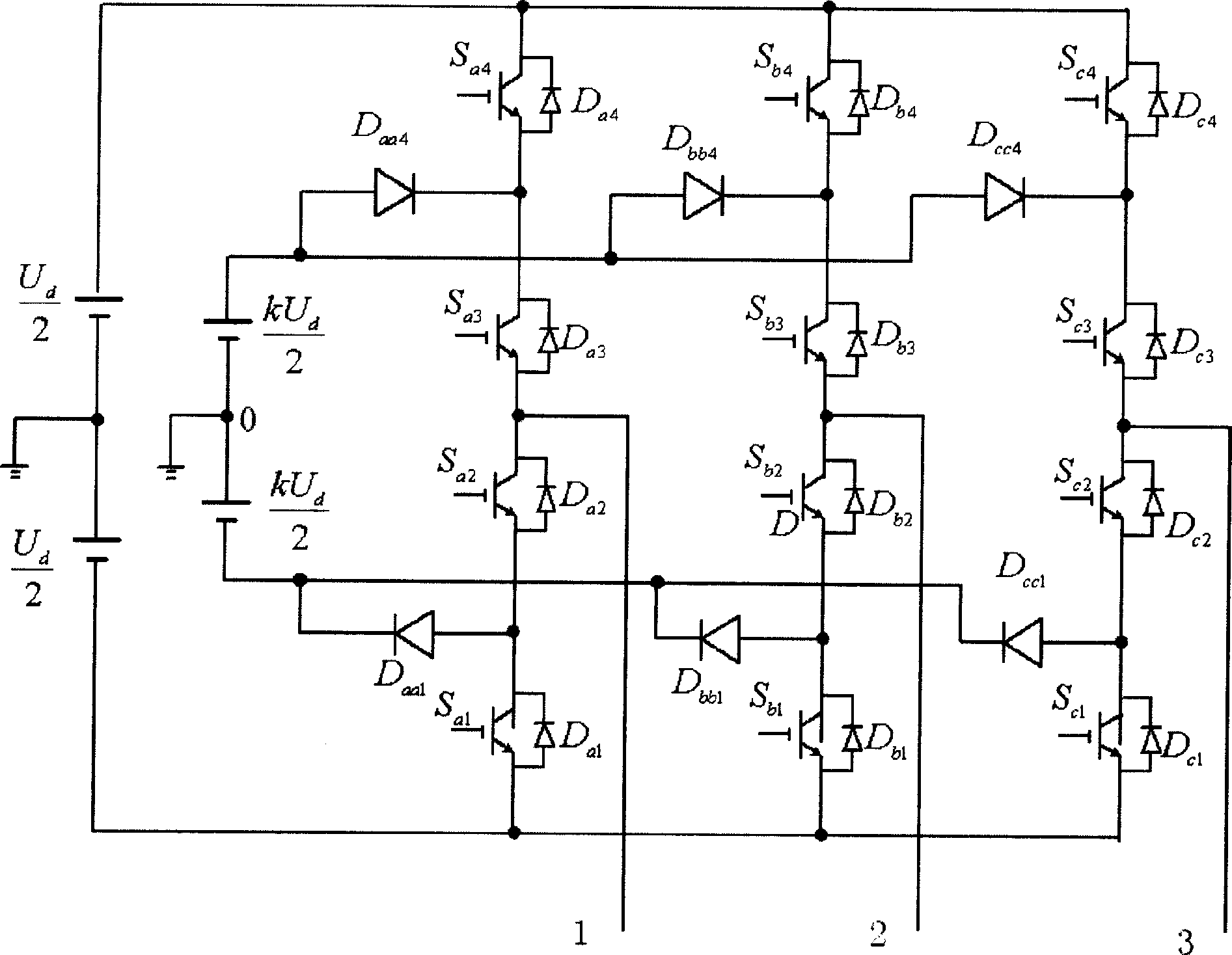
[0028] In order to facilitate the understanding of the present invention, the solution ideas of the present invention are first provided: (1) The present invention first constructs an asymmetric four-level output inverter circuit topology, which is referred to herein as a fourth-level asymmetric level topology. This topology is based on the establishment of a three-phase bridge type asymmetric fourth-level output inverter circuit, which is used as the basis of analysis; (2) In order to achieve the purpose of reducing switching loss and electromagnetic interference, the multi-level output needs to be optimized In the present invention, the optimized PWM method based on selective harmonic control is selected to finally produce an asymmetrical optimized PWM output voltage; (3) Because the optimized PWM method based on selective harmonic control is selected, the selective harmonic control is established The distribution relationship with the number of degrees of freedom of the variabl...


PUM


Abstract

This invention provides a multi-level transformation method, which sets up a optimized PWM math model with selective harmonic control as the restriction condition and residual voltage content as the optimized target function, resolves the model in optimization to get an optimized output level amplitude ratio K and the switch angle modulated by PWM, sets a multi-level circuit based on K and controls the output of the multi-level circuit based on the switch angle, which can greatly reduce switch frequency and related magnetic interference and covers multiple kinds of level topological structures. This invention also provides a multi-level circuit applying a dual-polarity asymmetrical level totological structure to generate voltage output of 7-stage level inverter load line.

Description

Technical field [0001] The invention belongs to the field of power semiconductor topological circuits and PWM (Pulse Width Modulation) control, especially multi-level conversion methods in high-power and ultra-high-power applications and multi-level circuits adopted by them. Background technique [0002] Electromagnetic interference and device switching losses caused by high-voltage and high-switching frequency power electronic application systems are the main obstacles to current high-power and ultra-high-power applications (see literature [1]), and are key issues that must be resolved at present. In order to reduce the related electromagnetic interference and switching loss, the soft switching technology represented by the improvement of the circuit topology structure can be used, but it will cause the circuit structure to be complicated. However, the existing Multilevel Converter method can only reduce the related electromagnetic interference problem to a certain extent. [00...

Claims


Application Information

Patent Timeline
IPC IPC(8): H02M7/48
Inventor 张慧程永光张平
Owner WUHAN UNIV
Learn More