Electro-hydraulic servo device

An electro-hydraulic servo and needle-shaped technology, applied in the direction of servo motor components, fluid pressure actuators, mechanical equipment, etc., can solve the problems of small market share of civilian products, inability to form competitiveness, unfavorable development of servo valves, etc., to achieve The effect of high power amplification, small dead zone and small volume

Inactive Publication Date: 2014-12-24
刘玉松
View PDF0 Cites 4 Cited by
  • Summary
  • Abstract
  • Description
  • Claims
  • Application Information

AI Technical Summary

Problems solved by technology

However, the products produced are mainly used in military fields such as aviation, aerospace, and ships, and have a small market share in civilian products.
At the same time, due to the fact that each production unit is fighting independently, lack of cooperation, and scattered forces, it is not conducive to the further development of servo valves, and it is impossible to form a strong competitiveness to compete with foreign products.

Method used


Image

  • Electro-hydraulic servo device

Examples


Embodiment 1

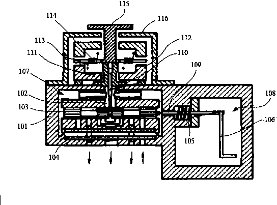
[0024] figure 1 A schematic structural diagram of an electro-hydraulic servo device according to an embodiment of the present invention is shown. Such as figure 1 The shown electro-hydraulic servo device includes a valve body 101, a nozzle 102, a spool valve core 103, a filter screen 104, a buffer spring 105, and a feedback pull rod 106. The valve body 101 is provided with a first cavity 107 and The second cavity 108, the filter screen 104, the spool valve core 103 and the nozzle 102 are all arranged in the first cavity 107, the nozzle 102 is connected with the upper part of the spool valve core 103, the filter The net 104 is located below the slide valve spool 103; a hole 109 is arranged between the first cavity 107 and the second cavity 108, and one end of the feedback pull rod 106 is connected to the hole 109, and the other end of the feedback pull rod 106 is One end is located in the second cavity 108 ; the feedback pull rod 106 is provided with a buffer spring 105 .

...

Embodiment 2

[0030] When the working pressure oil enters the valve from the oil inlet, it enters the oil cavity at both ends of the slide valve through two orifices respectively, and then flows out from the gap between the two nozzles and the needle baffle, and returns to the oil tank. When the control current is input, the needle baffle is in the middle of the two nozzle end faces. At this time, the pressure parameters of the two nozzle holes and the two fixed orifices are equal, so the pressures of the oil chambers at both ends of the slide valve are equal, and the slide valve in an intermediate equilibrium position. Close each channel, the servo valve has no pressure output. The control cylinder of the swash plate of the main hydraulic pump for traveling does not act, so that the main hydraulic pump does not do work. When the input control current I>0, the torque motor will generate a deflection torque, which drives the needle baffle to deflect an angle. At this time, due to the deflec...


PUM


Abstract

The invention discloses an electro-hydraulic servo device which comprises a valve body, a nozzle, a slide valve element, a filter screen, a buffer spring and a feedback pull rod. A first cavity and a second cavity are formed in the valve body. The filter screen, the slide valve element and the nozzle are all arranged in the first cavity. The nozzle is connected with the upper portion of the slide valve element. The filter screen is located below the slide valve element. A hole is formed between the first cavity and the second cavity. One end of the feedback pull rod is connected with the hole and the other end of the feedback pull rod is located in the second cavity. The buffer spring is arranged on the feedback pull rod. The electro-hydraulic servo device has the advantages of being small in size, high in power amplification, good in linearity, small in dead zone, high in response speed, smooth and reliable in motion, suitable for analog quantity and digital quantity and good in modulation effect.

Description

technical field [0001] The invention relates to the technical field of electrical equipment, in particular to an electro-hydraulic servo device. Background technique [0002] Electro-hydraulic servo devices are generally divided into two types according to the type of torque motor: moving coil type and permanent magnet type. Most of the traditional servo valves use permanent magnet torque motors. This type of servo valve can also be divided into two categories: nozzle baffle type and jet type. At present, most domestic manufacturers of servo valves mainly use the nozzle baffle type. Only the No. 704 Research Institute of China Shipbuilding Industry Corporation has produced jet tube servo valves in scale and series. The situation in foreign countries is also similar. Abex Company of the United States, a manufacturer specializing in the production of jet tube servo valves, has also been annexed by Park Company. However, because the jet tube servo valve has the characteristi...

Claims


Application Information

Patent Timeline
Patent Type & Authority Applications(China)
IPC IPC(8): F15B13/02
Inventor 刘玉松
Owner 刘玉松
Why Eureka
Try Eureka