Method and system for monitoring soil property side slope distributive fiber optic strain

A distributed optical fiber and strain monitoring technology, which is applied in the transmission system, pipeline system, electromagnetic wave transmission system, etc., can solve the problems that the distributed optical fiber sensing detection method has not been adopted.

Inactive Publication Date: 2007-01-24
NANJING UNIV
View PDF0 Cites 66 Cited by
  • Summary
  • Abstract
  • Description
  • Claims
  • Application Information

AI Technical Summary

Problems solved by technology

[0007] Distributed optical fiber sensing detectio

Method used


Image

  • Method and system for monitoring soil property side slope distributive fiber optic strain

Examples


Embodiment Construction

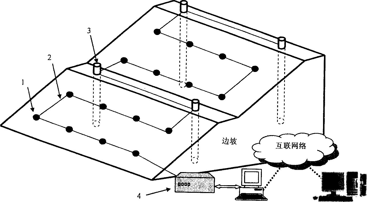
[0017] The invention is a soil slope distributed optical fiber strain measurement system, which relates to a monitoring method and system for soil slope surface and deep soil deformation based on distributed optical fiber sensing technology, including the following steps:

[0018] 1) Along the direction of the slope, the special optical cable is fixed point by point. The optical cable contains two sensing optical fibers, one is a tight sleeve optical fiber and the other is a loose sleeve optical fiber, which are used to measure strain and temperature respectively. Before fixing the optical cable and the anchor rod, it is necessary to open a groove with a depth of about 5-10 cm at the predetermined position. After the optical cable is placed in the soil groove, it is fixed with the anchor rod, and then covered with soil;

[0019] 2) The monitoring of deep soil deformation needs to be carried out with the help of inclinometer tubes. Paste the sensing fiber symmetrically on the o...


PUM


Abstract

This invention relates to a strain monitor system for slope distributed fibers, which lays out several parallel special optical cables along the slope or at least lays out one close to the slope top and the corner separately, adheres symmetrically two fibers on the outer surface of a tilt testing tube to get the distortion of deep soil helped by the strain of the tube, the special optical cables are melted orderly to constitute a sensor circuit to be connected to BOTDR, which links with remote computers via local computer and internet to constitute distributed fiber strain monitor system and gets the distortion or displacement of the slope by integrating and summing the measured strain distribution further to evaluate and preset to the side slope.

Description

1. Technical field [0001] The invention belongs to the technical field of geotechnical engineering monitoring, and relates to a soil slope monitoring system based on distributed optical fiber sensing technology. 2. Background technology [0002] my country is currently in a period of large-scale construction, and a large number of large-scale slope projects have appeared in various fields such as water conservancy, energy, and transportation, and landslide accidents occur frequently. Slope engineering monitoring is the main means and basis for determining slope stability, judging the sliding direction and speed of unstable slopes, mastering the law of slope development and evaluating the quality and effect of control measures. [0003] However, due to the complexity of the rock-soil medium and the large scope of the monitoring area, especially for a type of slope, it is necessary to establish a comprehensive three-dimensional monitoring network combining the surface and the ...

Claims


Application Information

Patent Timeline
IPC IPC(8): H04B10/12G01K11/32G01M3/00F17D5/02G01K11/322
Inventor 施斌张丹王宝军隋海波王小明朱友群魏广庆朴春德刘春陈峰军何亮胡盛李科刘杰张巍
Owner NANJING UNIV
Why Eureka
Try Eureka