Binocular active vision monitor suitable for precision machining

An active vision, precision machinery technology, applied in electrical program control, digital control and other directions, can solve the problems of limited viewing angle adjustment range, poor positioning accuracy, monitoring blind spots, etc., to achieve convenient modeling and calculation, easy description and expression, large scale. The effect of the range adjustment angle of view

Inactive Publication Date: 2007-01-31
YANSHAN UNIV
View PDF0 Cites 34 Cited by
  • Summary
  • Abstract
  • Description
  • Claims
  • Application Information

AI Technical Summary

Problems solved by technology

In the monitoring system with fixed cameras, the cameras (one or more) are fixed outside the working space and monitored from a fixed perspective. The advantage is that the mechanism and visual model are simple, but it requires a large field of view and cannot cover the entire visual space. Unable to change the angle of view, visual occlusion, poor positioning accuracy and other shortcomings; the hand-eye system connected to the series mechanism is to connect the camera to the end of the series mechanism, and adjust the angle of view of the camera by controlling the series mechanism. Although this mechanism has a certain ability to adjust the angle of view, but Its viewing angle adjustment range is limited, and it does not conform to the characteristics of the symmetry of the parallel mechanism and its working space, and there are also shortcomings such as monitoring blind spots and inflexible viewing angle conversion.

Method used


Image

  • Binocular active vision monitor suitable for precision machining
  • Binocular active vision monitor suitable for precision machining
  • Binocular active vision monitor suitable for precision machining

Examples


Embodiment Construction

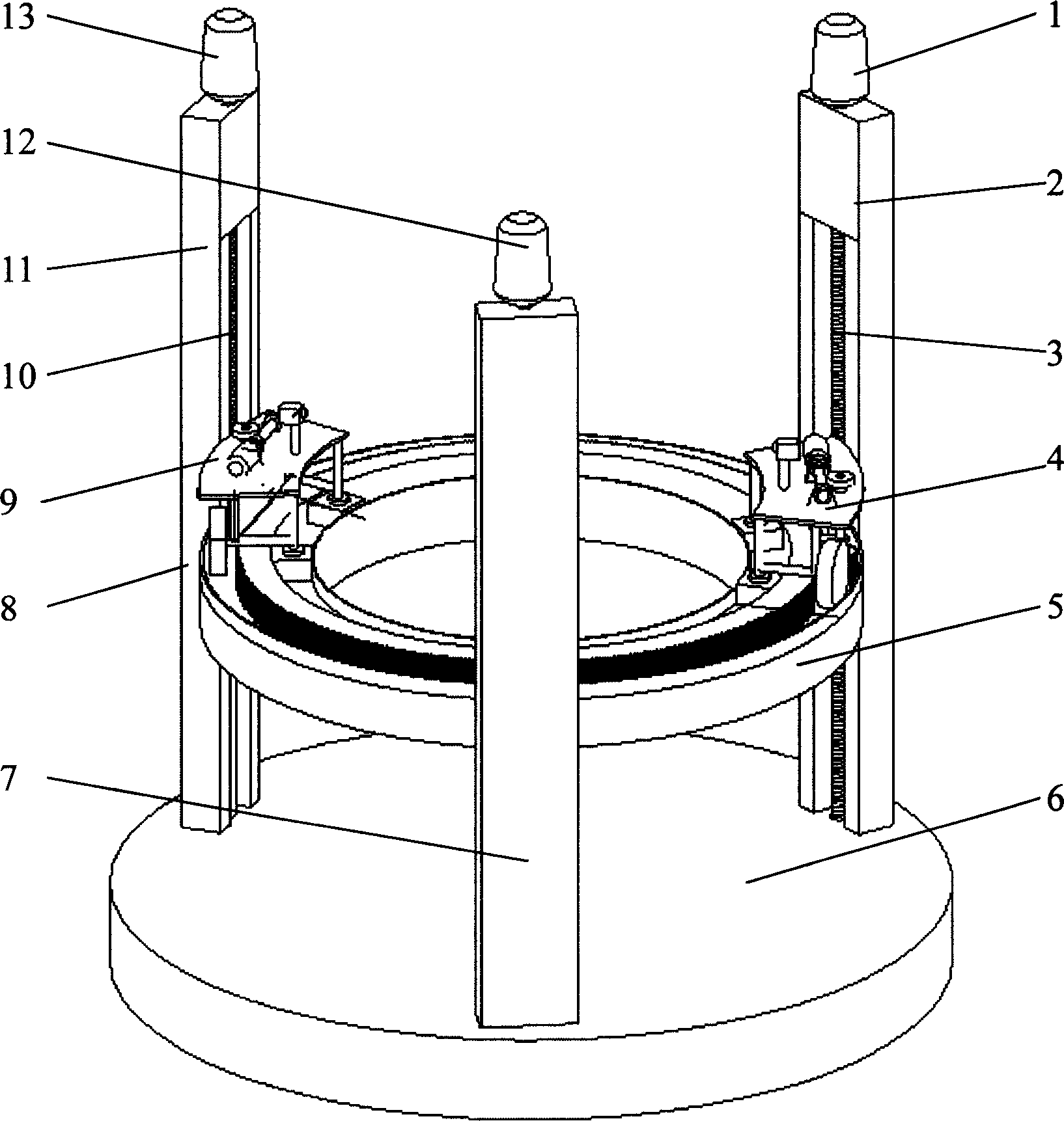
[0014] The binocular active visual monitoring device suitable for precision machining is independent of the parallel machine tool. Three symmetrically arranged brackets 2, 7, and 11 are fixed on the base 6. Each bracket is equipped with upper and lower slide rails, and each slide rail is connected to each other. Parallel and perpendicular to the plane of the base 6; slide blocks are installed on each slide rail, the upper and lower slide rails and slide blocks adopt screw nut structure, and lead screws 3 and 10 are installed in the three brackets (bracket 7 also has the same screw nuts as 3 and 10). lead screw), the slider 8 is processed with internal threads (the circular guide rail 5 and the brackets 2 and 7 have the same slider as 8), the circular guide rail 5 is fixedly connected with the three sliders 8, and the circular guide rail is kept parallel to the base flat. The stepping motors 1, 12, 13 are installed on the tops of the three supports 2, 7, 11, and the output ends...


PUM


Abstract

The invention relates to a binocular initiative vision monitoring device for precision machining. The feature is that it fixes three supports on base, and sliding rails are installed in the three supports and plumbing to bottom plane, sliding blocks are installed in the sliding rail, the round guiding rail connecting to the three sliding blocks, two dollies installed on the round guiding rail, each dollies having a cradle head that is installed a video camera. The base line and location between the two video cameras would be adjusted by sliding on the guiding rail. The vision system could flexibly adjust the observing anger. It has the advantages of parallel structure, simple moving mode and simple vision computing mode.

Description

technical field [0001] The invention relates to the field of visual monitoring of mechanical processing, in particular to a binocular active visual device for monitoring the working space of precision machining of parallel machine tools. Background technique [0002] Parallel machine tool is a new type of CNC processing equipment with parallel mechanism as the main body. Compared with traditional CNC machine tools, parallel machine tool is easy to realize six-axis linkage, and it is a kind of virtual axis machine tool. [0003] The emergence of parallel mechanisms can be traced back to 1931. Gwinnett proposed an entertainment device based on spherical parallel mechanisms in his patent. In 1962, Gough invented a six-degree-of-freedom tire detection device based on parallel mechanisms. In 1965, German Stewart For the first time, the mechanism invented by Gough was studied in the sense of mechanism, and it was extended and applied to the motion generating device of the flight s...

Claims


Application Information

Patent Timeline
Patent Type & Authority Applications(China)
IPC IPC(8): G05B19/18
Inventor 孔令富赵力强窦燕
Owner YANSHAN UNIV
Why Eureka
Try Eureka