Gas-liquid parallel current guide floating valve

A float valve and gas-liquid technology, applied in the field of guided float valves, can solve the problems of incomplete elimination of reverse airflow against airflow, unsatisfactory energy consumption and mass transfer efficiency, increased energy consumption, etc., to achieve increased specific surface area, increased gas Opportunities for liquid contact and reduction in operating energy consumption

Inactive Publication Date: 2007-02-07
西安汉术化学工程股份有限公司
View PDF2 Cites 2 Cited by
  • Summary
  • Abstract
  • Description
  • Claims
  • Application Information

AI Technical Summary

Problems solved by technology

There is a big problem in the existing float valve: part of the gas flushed out from the float valve is flushed out from the liquid-facing surface of the valve, and forms a countercurrent flow with the liquid, which increases the resistance to the liquid flow and consumes energy. At the same time, a part of the gas rushes out from both sides of the valve, forming a hedge between the valve and the valve, which increases the mist entrainment and affects the mass transfer efficiency
However, it cannot completely eliminate the reverse air flow and the opposing air flow between the valves on both sides, so the reduction of energy consumption and the improvement of mass transfer efficiency are not ideal.

Method used


Image

  • Gas-liquid parallel current guide floating valve
  • Gas-liquid parallel current guide floating valve
  • Gas-liquid parallel current guide floating valve

Examples


Embodiment 1

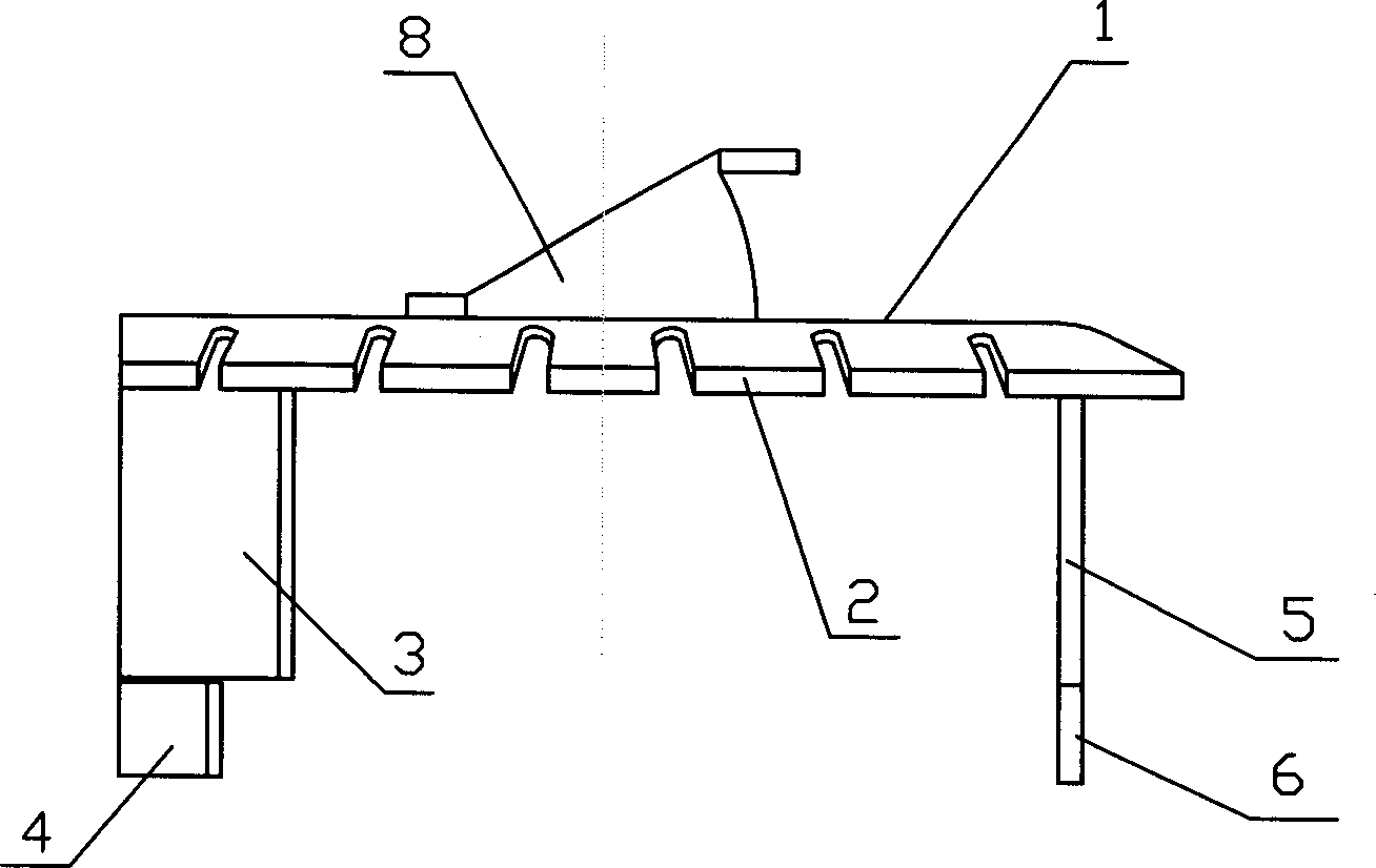
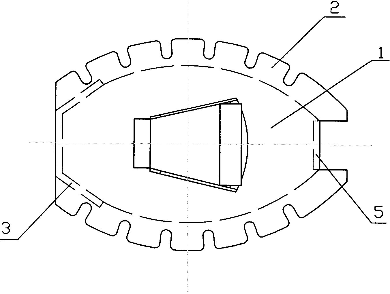
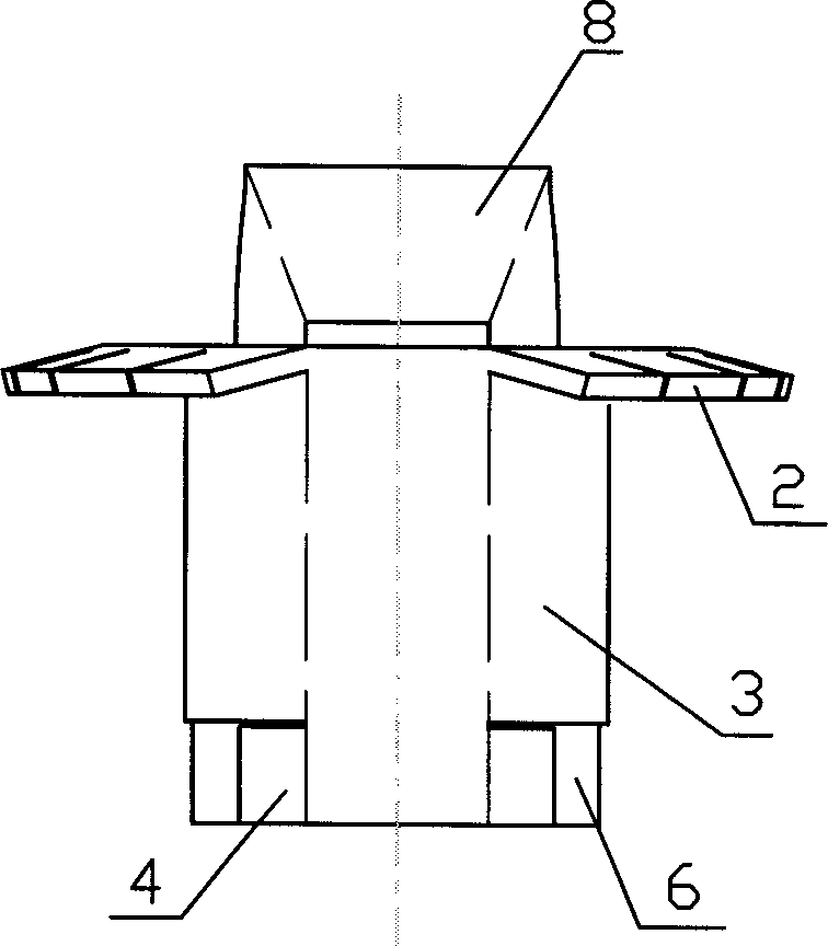
[0036] see Figure 1~4 , 9. The float valve has an elliptical bonnet 1, on both sides of the short axis of the bonnet there are flower-toothed guide pieces 2 bent and pressed down, and on one end of the long axis of the bonnet is provided with a vertical downward bend The liquid-receiving plate 3, the liquid-receiving baffle in this example is made in this way: the small arc surface at one end of the long axis of the elliptical bonnet is bent vertically downward, and a rectangular vertical plate is below the bending line, and the folded Cut a section symmetrically on both sides of the bending line, and then bend the vertical plate of the cut part toward the valve cover to form a trapezoidal liquid-receiving plate with a small front and a large rear. Avoid edges and corners as much as possible to reduce the resistance to the liquid; there is a valve stirrup 4 at the lower end of the liquid-receiving plate 3, before the valve body is installed, the valve stirrup bends toward the...

Embodiment 2

[0040] see Figures 13 to 16 In this example, a grid bar 2' bent vertically downwards is added between the petals of the tooth-shaped guide piece 2, the grid bar is formed by retaining the spacer between the petals and then vertically bent, and the grid bar can be The gas rushing out from both sides of the valve body is cut to refine the bubbles and further improve the mass transfer efficiency. In addition, this example presents a structure in which the center of gravity of the small float valve 8 shifts toward the direction of the liquid-receiving plate, so as to realize the gradual opening function of the main float valve.


PUM


Abstract

The invention relates to a guide float valve, which comprises: an ellipses valve cover whose short axle has spindle guide plate bended at two sides, and long axle has one ellipses liquid plate at one end, wherein the lower end of liquid plate has one valve stop pin; another end of said long axle has a vertical bended valve leg; the lower end of said leg has another valve stop pin; the valve leg has a ventilate hole; the valve cover has a guide small float valve; the liquid plate can completely block the airflow reversed to the liquid, and via using liquid plate and guide small float valve to guide the gas, the gas will be guided out, and the convective overshooting between valves can be avoided, to reduce the liquid gradient and reduce the energy consumption.

Description

Technical field [0001] The invention relates to a float valve in the field of petrochemical industry, in particular to a guide float valve. Background technique [0002] In the prior art, the valve tray is widely used in the petrochemical industry, and it is mainly composed of a tray body and a valve mounted on the tray. When working, the liquid phase flows from one side of the tower wall to the tray from top to bottom, and flows along the diameter direction of the tray, and then flows to the lower section from the other side of the tower wall, and the gas phase rushes to the tray from bottom to top , lift the float valve on the tray, and punch out from the air guide hole on the side of the float valve and the top cover, and contact with the liquid phase for mass transfer. There is a big problem in the existing float valve: part of the gas flushed out from the float valve is flushed out from the liquid-facing surface of the valve, and forms a countercurrent flow with the li...

Claims


Application Information

Patent Timeline
Patent Type & Authority Applications(China)
IPC IPC(8): B01D3/20
Inventor 韩刚
Owner 西安汉术化学工程股份有限公司
Why Eureka
Try Eureka