Automatic thermal riveting method and automatic thermal riveting machine for chain pin shaft

A technology of hot riveting machine and pin shaft, which is applied in the direction of metal chains, etc., can solve the problems that the thermal efficiency cannot be fully utilized, the outer chain plate cannot be removed, the pin shaft and the outer chain plate are disengaged and disassembled, etc.

Inactive Publication Date: 2007-02-07
JIANGSU SHUANGLING CHAIN TRANSMISSION
View PDF0 Cites 22 Cited by
  • Summary
  • Abstract
  • Description
  • Claims
  • Application Information

AI Technical Summary

Problems solved by technology

[0002] At present, the traditional pin riveting method in my country's chain industry is to use the press mold to press the double-sided outer side of the end of the pin shaft, so that the pin shaft is thickened in one direction (about 3-4%), which is not affected by the lateral force. It meets the requirements for the transmission chain, but for those conveyor chains subject to lateral force, if the riveting surface is small, it is easy to disengage and disassemble the pin shaft and the outer chain plate, so it is required to adjust the pin shaft Ball riveting is carried out on the end of the pin shaft, so that the head of the pin shaft is thickened as a whole, and the outer chain plate cannot be removed
There are many methods of ball riveting, one of which is to remove the hardness of the end of the pin shaft in advance, and then perform cold pressure ball riveting. In this way, the required pressure is very large, and the increase in deformation of the riveting head is not as large as that of hot riveting; the other is One is hot riveting after heating with gas on the spot. The disadvantage is that the heat of the gas will anneal the chain plate and weaken the strength of the chain; a more advanced method is to move the pin shaft of the chain to the previous station, Heating under the induction coil, and then moving to the riveting die of the punch press at the next station for riveting. Although this method will not anneal the chain plate, the chain moving process takes a long time, and the thermal efficiency cannot be fully utilized, which is a waste of time. energy; in addition, there are still problems of high labor intensity and low work efficiency

Method used


Image

  • Automatic thermal riveting method and automatic thermal riveting machine for chain pin shaft
  • Automatic thermal riveting method and automatic thermal riveting machine for chain pin shaft
  • Automatic thermal riveting method and automatic thermal riveting machine for chain pin shaft

Examples


Embodiment Construction

[0030] The present invention is described in further detail below in conjunction with the embodiment that accompanying drawing provides.

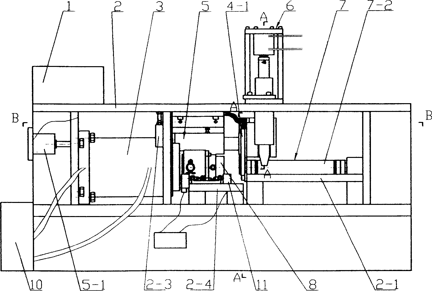
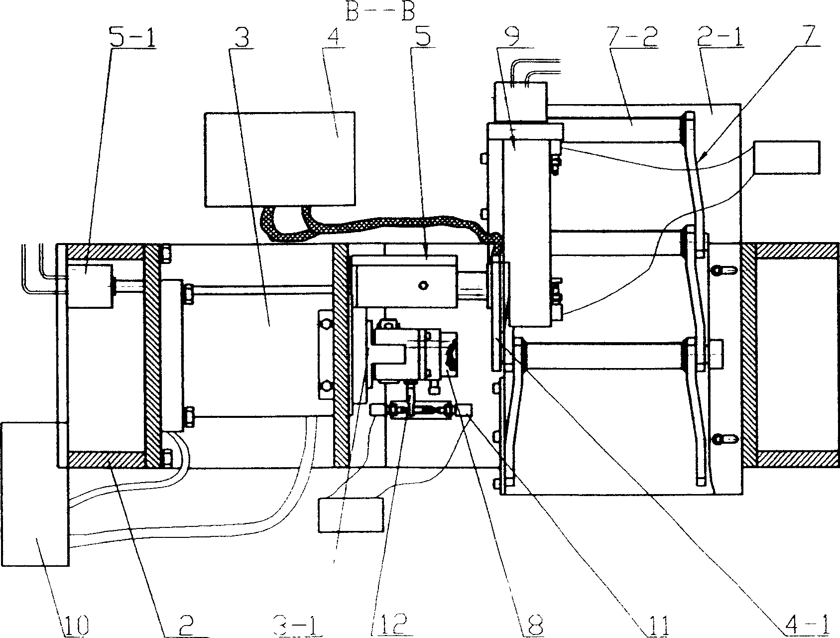
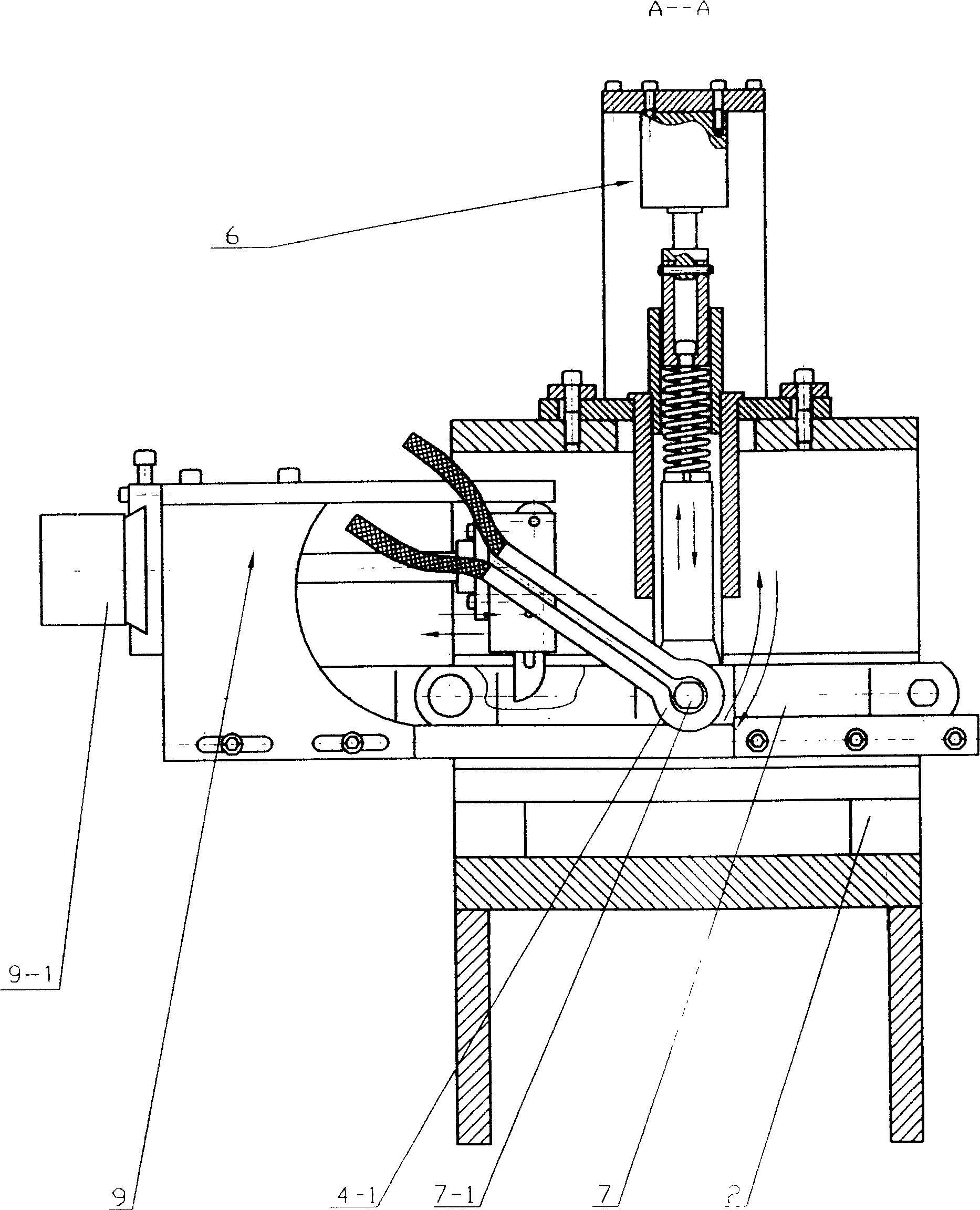
[0031] see figure 1 , 2 , 3, 4, 5, and 6, a chain pin automatic hot riveting method of the present invention, a chain pin automatic hot riveting method, a number of chain links combined into strips are placed on the workbench 2-1 , position the chain link 7 where the pin shaft 7-1 to be riveted is located, so that the end of the pin shaft 7-1 to be riveted is axially facing the riveting die 8, and the tail of the pin shaft 7-1 is axially limited; then the electromagnetic induction The heating ring 4-1 moves to the end of the pin shaft 7-1 to heat the end of the pin shaft 7-1; after heating to the riveting temperature, the electromagnetic induction heating ring 4-1 withdraws in time; The end of the pin shaft 7-1 is riveted; the riveting head mold 8 is returned; the chain link 7 where the riveted pin shaft 7-1 is located is loosened; the ch...


PUM


Abstract

The invention relates to an automatic hot rivet method of chain pin axle and a relative rivet machine, wherein said method comprises: arranging several chain sections on the work bench; positioning the chain section of riveted pin axle, to aim the end of pin axle to the rivet mould and aim the tail of pin axle axially; then moving the electromagnetic induction heating coil to be end of pin axle, to heat the end; heating to the rivet temperature, removing the electromagnetic induction heating coil; riveting the pin axle end with rivet mould; returning the rivet mould; loosing the chain section; then moving the chain section to make the next pin axle on site. The heat riveter comprises a frame, a hydraulic cylinder, a controller, an electromagnetic induction heating coil feeder and a chain positioning device. And the invention has high rivet speed and high working efficiency.

Description

technical field [0001] The invention relates to a chain assembly method and equipment, in particular to a hot riveting method and machinery for chain pins. Background technique [0002] At present, the traditional pin riveting method in my country's chain industry is to use the press mold to press the double-sided outer side of the end of the pin shaft, so that the pin shaft is thickened in one direction (about 3-4%), which is not affected by the lateral force. It meets the requirements for the transmission chain, but for those conveyor chains subject to lateral force, if the riveting surface is small, it is easy to disengage and disassemble the pin shaft and the outer chain plate, so it is required to adjust the pin shaft Ball riveting is carried out at the end of the pin shaft, so that the head of the pin shaft is overall thickened, and the outer chain plate cannot be removed. There are many methods of ball riveting, one of which is to remove the hardness of the end of the ...

Claims


Application Information

Patent Timeline
Patent Type & Authority Applications(China)
IPC IPC(8): B21J15/08B21J15/44B21J15/16B21J15/28B21L9/06B21L11/14
Inventor 金文龙李奇伟谈光成
Owner JIANGSU SHUANGLING CHAIN TRANSMISSION
Why Eureka
Try Eureka