Hydraulic chain tensioner assembly

A chain tensioning device and tensioning device technology, applied in the direction of transmission, belt/chain/gear, mechanical equipment, etc., can solve the problem of chain loosening and other problems

Inactive Publication Date: 2007-02-07
GM GLOBAL TECH OPERATIONS LLC
View PDF0 Cites 6 Cited by
  • Summary
  • Abstract
  • Description
  • Claims
  • Application Information

AI Technical Summary

Problems solved by technology

Over time, the chain may loosen due to repeated loading and unloading cycles during torque reversal

Method used


Image

  • Hydraulic chain tensioner assembly
  • Hydraulic chain tensioner assembly
  • Hydraulic chain tensioner assembly

Examples


Embodiment Construction

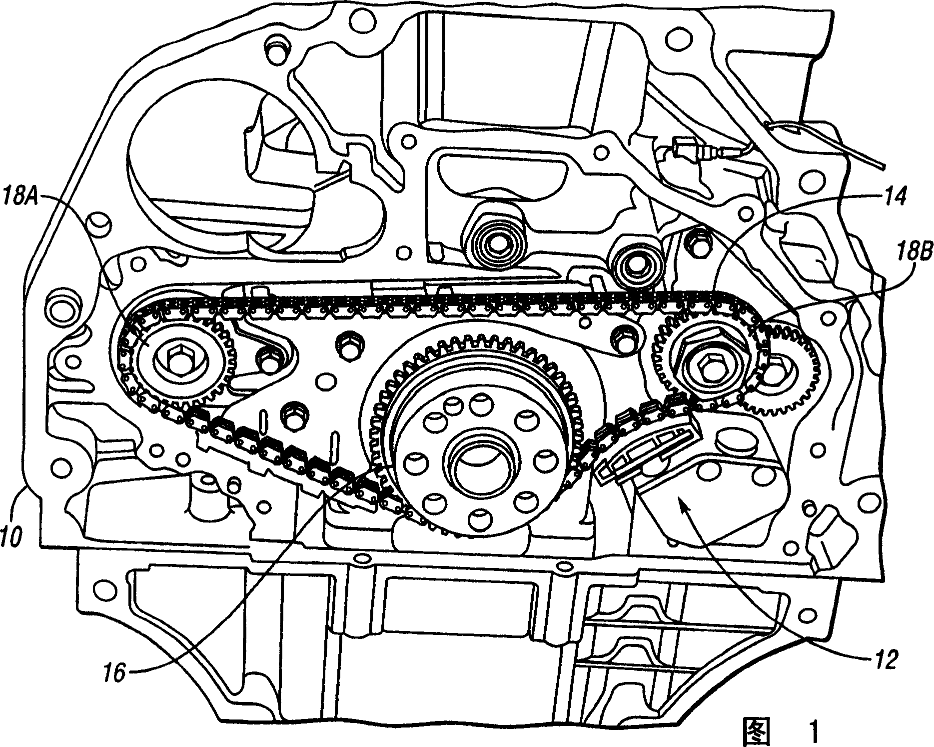
[0019] Referring to the drawings, wherein like reference numerals refer to like components, FIG. 1 shows an engine 10 having a hydraulic chain tensioner assembly 12 tensioning a balancer drive chain 14 . It should be noted that although the hydraulic chain tensioner assembly 12 is applied to the balancer drive arrangement of FIG. Valve train drive. Crank sprocket 16 powered by engine 10 and rotating at engine speed drives balancer chain 14 which rotates countershaft sprockets 18A and 18B to drive a balance shaft connected thereto (balance shaft not shown). out). The arrangement of the crank sprocket 16 and balance sprockets 18A, 18B requires encapsulation of the hydraulic chain tensioner assembly 12 as shown, which means that it contacts the chain 14 in a short span. Tensioning the chain 14 over such a short span increases the noise caused by the interaction of the chain with the sprockets 16, 18A, 18B.

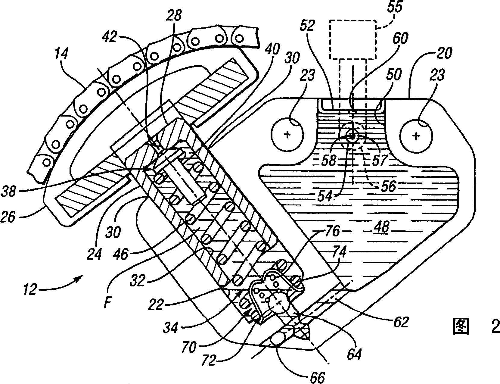
[0020] Referring to FIG. 2 , the hydraulic chain tensioner assembly 1...


PUM


Abstract

A hydraulic chain tensioner assembly includes a plunger slider received within an opening in a tensioner body to define a controlled clearance and a substantially fluid-tight chamber. Pressure in a supply reservoir that is in fluid communication with the fluid-tight chamber is controlled to a relatively low level by appropriate sizing of the feed orifice and a bleed orifice in communication with the supply reservoir. Thus, apply force of a shoe connected to a plunger on a chain is a function of stiffness of a main spring that biases the plunger outward, and is not substantially affected by pressure of a fluid source supplying fluid to the reservoir. A method of manufacturing a hydraulic chain tensioner assembly is also provided.

Description

technical field [0001] The present invention relates to a hydraulic chain tensioner assembly comprising a fluid tight chamber connected to a pressure controlled supply reservoir. Background technique [0002] Chain drives emerged as work aids within modern automobile engines. For example, chain drives have been used to drive complex valve trains, balance shafts, oil pumps, high pressure fuel injection pumps and water pumps. With the increased packaging complexity and its impact on chain drive layout and design, dedicated tensioning devices have become a practical need to ensure the overall functional performance of the chain drive. Over time, the chain may become loose due to repeated loading and unloading cycles during torque reversal. Hydraulic chain tensioner assemblies must balance applying sufficient force to tension slack chain to maintain chain function while minimizing chain noise. The noise caused by high loads may be referred to as "rattle" and "cough" and is pr...

Claims


Application Information

Patent Timeline
Patent Type & Authority Applications(China)
IPC IPC(8): F16H7/08
CPCF16H2007/0812F16H7/0848F16H2007/0859F16H2007/0806
Inventor J·M·比德莫尔
Owner GM GLOBAL TECH OPERATIONS LLC
Why Eureka
Try Eureka