
Ultrasonic method for flow measurement and device thereof

A flow measuring device and ultrasonic technology, applied in the direction of measuring device, measuring flow/mass flow, liquid/fluid solid measurement, etc. The effect of improving measurement accuracy and reducing influence

Inactive Publication Date: 2007-02-07
INST OF ACOUSTICS CHINESE ACAD OF SCI +1
View PDF0 Cites 7 Cited by
  • Summary
  • Abstract
  • Description
  • Claims
  • Application Information

AI Technical Summary

Problems solved by technology

However, the traditional downhole time-of-flight ultrasonic measurement device greatly changes the flow field to be measured. At the same time, when the measured fluid is oil with high viscosity, the surface of the transducer will adhere, which will affect the accuracy of flow measurement.

Method used

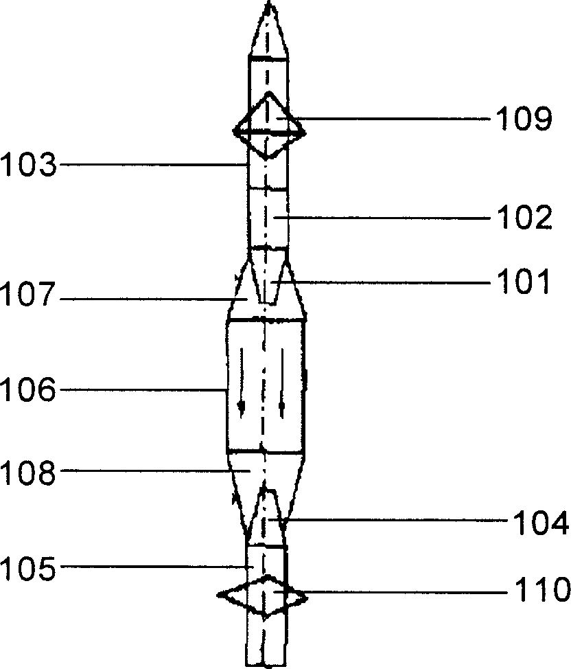
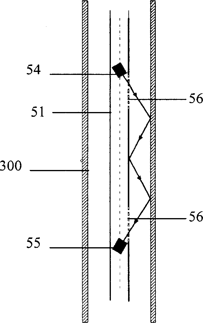

Image

  • Ultrasonic method for flow measurement and device thereof
  • Ultrasonic method for flow measurement and device thereof
  • Ultrasonic method for flow measurement and device thereof

Examples


Embodiment 1

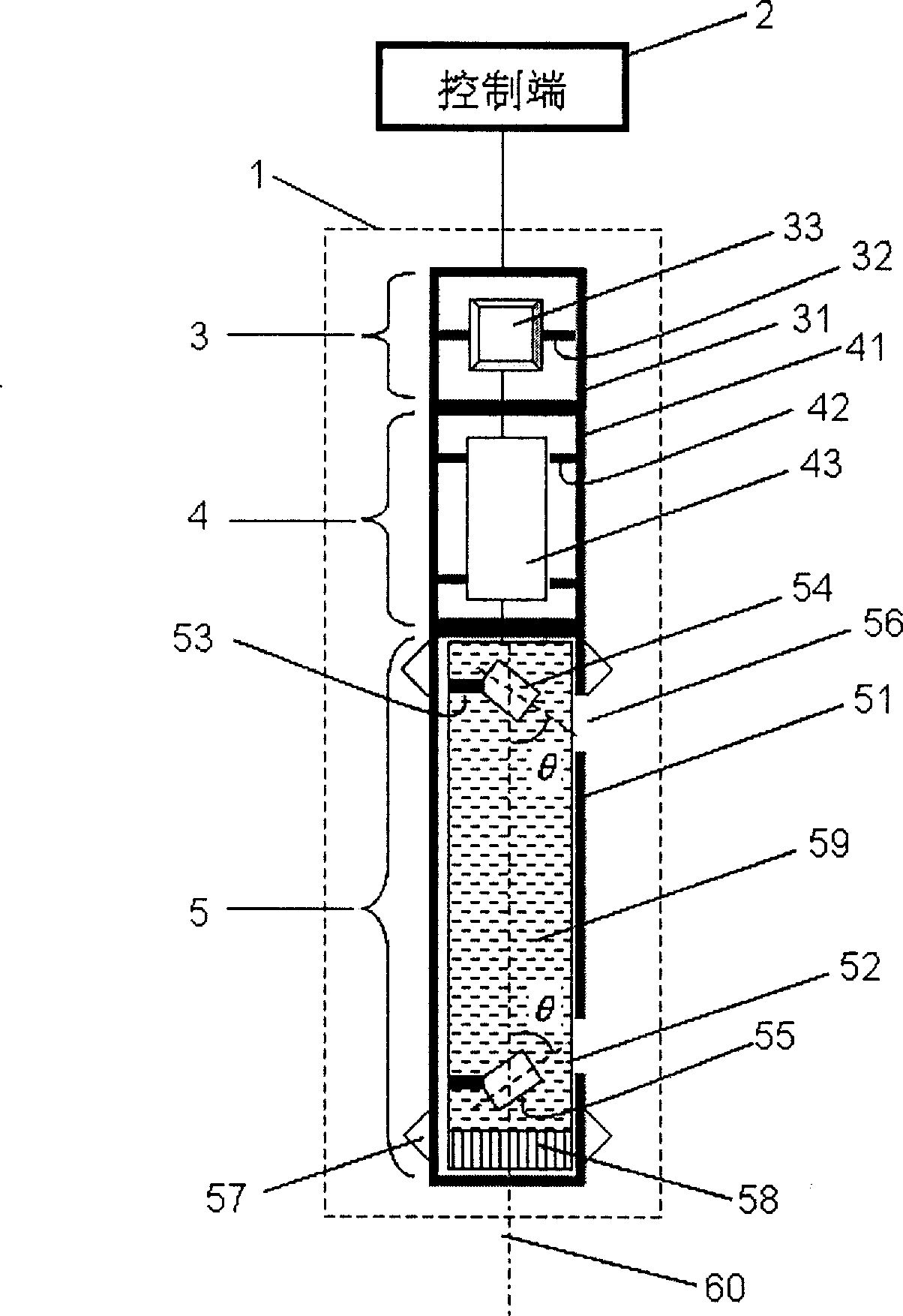
[0041] refer to figure 2 An ultrasonic flow measuring device is manufactured, wherein the measuring end 1 will be used in an underground well, the control end 2 is above the ground, and the measuring end 1 and the control end 2 are connected by cables.

[0042] In order to allow the device to withstand enormous pressure when working in deep wells, the first protection tube 31, the second protection tube 41 and the mechanical frame 51 are all made of stainless steel plate material with a thickness of 5mm, and are sequentially connected together by threads; The first protective tube 31 has a length of 500 mm and a diameter of 45 mm; the second protective tube 41 has a length of 800 mm and a diameter of 45 mm; the mechanical skeleton 51 has a length of 900 mm and a diameter of 45 mm.

[0043] The transmission module 33 of the transmission sub-section 3 adopts the 8248E special transmission module of Western Atlas Company, which is responsible for loading the encoded signal compl...

Embodiment 2

[0061] refer to figure 2 Make an ultrasonic flow measurement device. Wherein, the included angle between the emission directions of the first transducer 54 and the second transducer 55 and the acoustic system axis 60 is θ=50°; Two sets of compressible lantern-like support structures at the end.

[0062] Others are the same as in Example 1.

Embodiment 3

[0064] refer to figure 2 Make an ultrasonic flow measurement device. Wherein, the included angle between the emission directions of the first transducer 54 and the second transducer 55 and the acoustic system axis 60 is θ=55°.

[0065] Others are the same as in Example 1.


PUM


Abstract

The disclosed ultrasonic flow measuring device comprises: a measurement end with a transmission node, an electronic node, and a sound node; and a control end, wherein the former sound node comprises: a mechanical frame with a thin-wall cylinder clung to its inner wall, and a first and second energy transducer inclined on cylinder ends. Besides, the corresponding measuring method comprises: 1) arranging the measurement device into the target center; 2) measuring the sound reflux transmission time t1 and the downstream transmission t2 for delta t=ABS (t1-t2); 3) obtaining the liquid speed by v=c2delta t / 2L. This invention has well precision and fit to avoid oil pollution.

Description

technical field [0001] The invention relates to a flow measuring method and a flow measuring device, in particular to an ultrasonic flow measuring method and a flow measuring device suitable for underground oil flow measurement. Background technique [0002] In downhole oil flow measurement, the flow measurement device is required to have a wide dynamic range and high measurement accuracy. Due to the high viscosity and non-conductivity of downhole crude oil, traditional turbine or electromagnetic flowmeters cannot be used, and ultrasonic flowmeters are a viable option. There are generally three types of ultrasonic flowmeters: Doppler ultrasonic flowmeters, transit time ultrasonic flowmeters, and phase difference ultrasonic flowmeters. The Doppler ultrasonic flowmeter requires that the measured fluid contains air bubbles or suspended particles; Document 1: Several improvements of the transit time ultrasonic flowmeter, the Journal of Shenyang University of Technology, Vol.24,...

Claims


Application Information

Patent Timeline
Patent Type & Authority Applications(China)
IPC IPC(8): G01F1/66
Inventor 张海澜卢涛林伟军张澄宇王东
Owner INST OF ACOUSTICS CHINESE ACAD OF SCI
Learn More