
Surging current detecting circuit

A surge current, testing circuit technology, applied in power supply testing, measuring current/voltage, AC/pulse peak measurement, etc., can solve the problems of inaccurate measurement, insufficient energy, short power supply time, etc., to achieve accurate test results and test results. Long-lasting, energy-rich effect

Inactive Publication Date: 2007-02-07
HONG FU JIN PRECISION IND (SHENZHEN) CO LTD +1
View PDF0 Cites 11 Cited by
  • Summary
  • Abstract
  • Description
  • Claims
  • Application Information

AI Technical Summary

Problems solved by technology

Since the test voltage changes once every 0.02s, the power supply time is too short and the energy is insufficient, often resulting in inaccurate measurement and low test data

Method used


Image

  • Surging current detecting circuit

Examples


Embodiment Construction

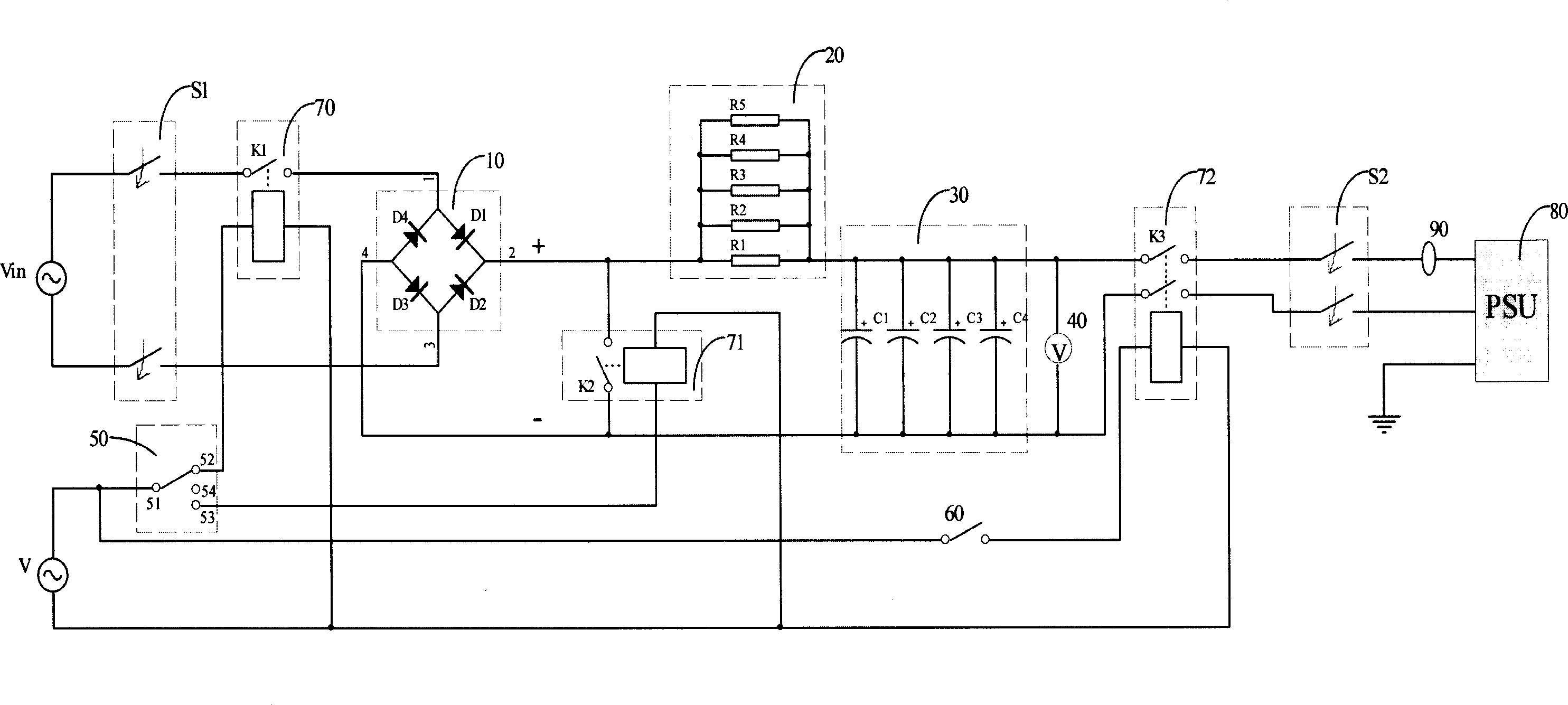
[0008] see figure 1 The surge current test circuit of the present invention includes an input AC power supply Vin, an AC-DC conversion circuit (in this preferred embodiment, a bridge circuit 10), a resistance part 20, a capacitor part 30, a voltmeter 40 . A power supply to be tested (PSU) 80 and a current testing instrument (a current gun 90 in this preferred embodiment).

[0009] The bridge circuit 10 includes a port 1, a port 2, a port 3 and a port 4, wherein a first diode D1 is forwardly connected between the port 1 and the port 2, and a reverse direction is connected between the port 2 and the port 3. A second diode D2 is connected to the direction, a third diode D3 is connected reversely between the port 3 and the port 4, and a fourth diode D4 is connected forwardly between the port 4 and the port 1 . The bridge circuit 10 is used for converting AC voltage into DC voltage. The AC-DC conversion circuit is not limited to the bridge circuit 10 , and other AC-DC conversion ...


PUM


Abstract

The test circuit for surge current comprises: an ac power, a capacitor to provide test voltage, an ac / dc conversion circuit to convert the ac power into dc and charge the capacitor, and a current test device to obtain the serge current value.

Description

【Technical field】 [0001] The invention relates to a surge current test circuit of a computer switching power supply, in particular to a surge current test circuit which can provide a stable test voltage and has sufficient energy. 【Background technique】 [0002] A computer switching power supply is a converter that converts alternating current to direct current required for computer work. When the computer is turned on, the switching power supply will generate a sudden peak current, that is, an inrush current. Excessive surge current will cause damage to switching power supply components. [0003] For this reason, computer manufacturers must test the surge current of the switching power supply to ensure that the surge current is within a safe range. The test voltage used for testing the surge current is generally directly provided by a programmable AC power supply, and the voltage value and frequency of the AC power supply can be set freely. The input voltage range of swit...

Claims


Application Information

Patent Timeline
Patent Type & Authority Applications(China)
IPC IPC(8): G01R19/00G01R19/04G01R31/42
CPCG01R31/42
Inventor 黄俭雄
Owner HONG FU JIN PRECISION IND (SHENZHEN) CO LTD
Learn More