
Gas chromatograph

A gas chromatograph and gas technology, applied in the field of gas chromatograph, can solve the problem of low flow rate, achieve low power consumption, improve lateral sensitivity, and promote commercial success

Inactive Publication Date: 2007-02-07
ENVIRONMENTAL STUDIES LTD
View PDF6 Cites 20 Cited by
  • Summary
  • Abstract
  • Description
  • Claims
  • Application Information

AI Technical Summary

Problems solved by technology

In some detector types this flow may still be too low

Method used


Image

  • Gas chromatograph
  • Gas chromatograph
  • Gas chromatograph

Examples


Embodiment Construction

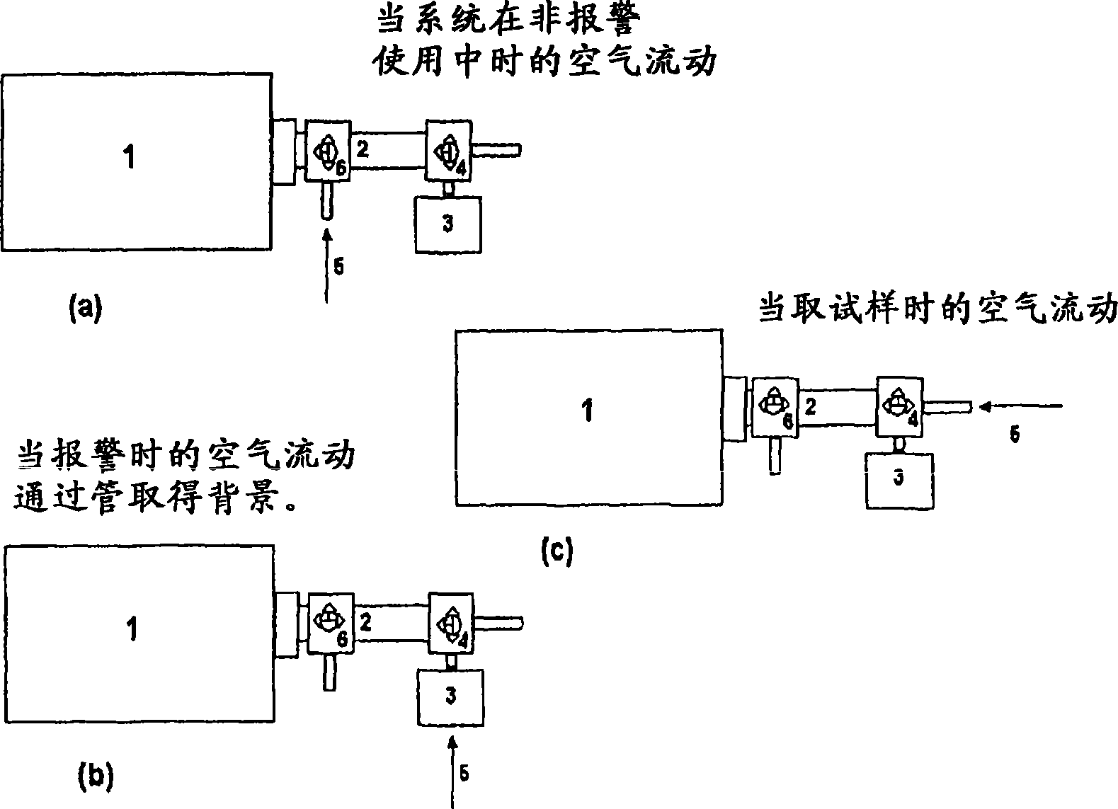
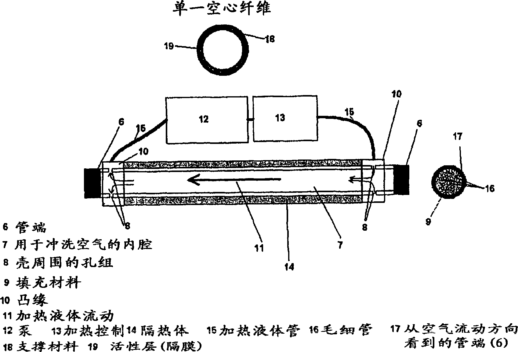
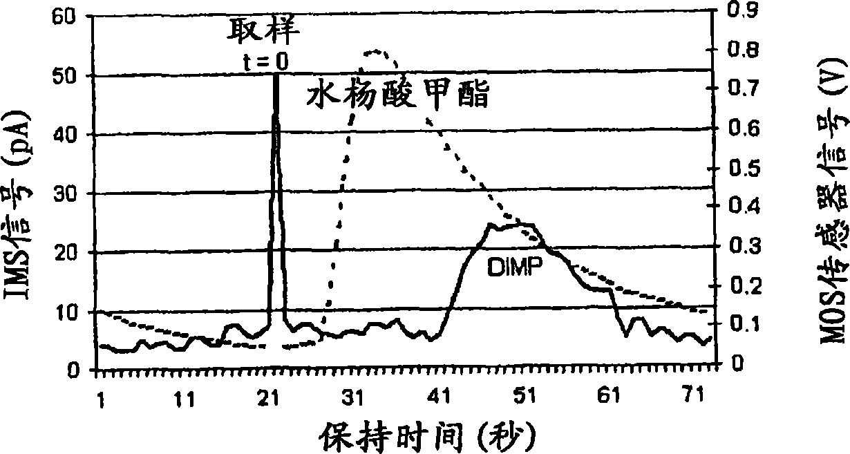
[0032] figure 1 A preferred embodiment of the use of a hollow fiber capillary membrane bundle (2) as a GC column in combination with a chemical detector (1) is described. The sampling device consists of valve (4), vapor adsorption filter (3), gas inlet (5) and optional auxiliary valve (6). The position of the valve (4) determines whether the sample flows through the filter (valve switched to position 4b) or directly (valve switched to position 4c) to the hollow fiber bundle based polycapillary GC column (2). The instant of switching the valve from position 4b to 4c determines t=0 for the holding time.

[0033] also expressed in figure 1 Another preferred embodiment in the ® relates to the auxiliary valve (6) used to control whether the hollow fiber bundle based GC column is in use (position 6b or 6c) or not in use (position 6a). Faster response times are possible when hollow fiber bundles are not used (position 6a), but more specific resolution with less cross-sensitivity i...


PUM

PropertyMeasurementUnit
lengthaaaaaaaaaa

Abstract

The invention relates to a gas chromatograph for the analysis of gas samples. It has a feed arrangement for feeding the sample, an open tubular capillary column for separating the components of the sample, temperature control means for controlling the temperature of the column, and a detector for detecting the separated components of the sample. The efficiency has been improved and a convenient hand-held version has been made possible by constructing the column of a bundle of open tubular capillaries having a gas permeable wall comprising a polymer membrane. The invention also relates to the use of such a column together with a detector for identifying gaseous samples.

Description

technical field [0001] The invention relates to a gas chromatograph for sample analysis, the gas chromatograph having a feeding device for feeding the sample, an open tubular capillary column for separating the components of the sample, a temperature for controlling the temperature of the column A control unit, and a detector for detecting the separated components of the sample, wherein the column comprises a bundle of open tubular capillaries. Background technique [0002] The chemical state of a gas-phase sample is formed by vaporized or gaseous chemical species mixed with the surrounding medium, typically ambient air. Instead of air, the medium can be process gas or vacuum. Detectors are used to detect and resolve defined chemical species in defined surrounding media. [0003] A property used in chemical detectors is their ability to convert chemical states into electrical signals and transmit the signals for further processing. Typically its purpose is to perform a qu...

Claims


Application Information

Patent Timeline
Patent Type & Authority Applications(China)
IPC IPC(8): G01N30/02B01D53/10B01D63/02B01D53/02B01D61/00G01N30/30G01N30/60
CPCG01N2030/0095B01D53/02G01N30/6043B01D63/02G01N30/6073B01D61/00B01D2313/22G01N30/6069B01D63/031B01D2313/221
Inventor 海克·帕卡尼恩米克·尤特里埃恩
Owner ENVIRONMENTAL STUDIES LTD
Learn More