Camera module

A technology for cameras and imaging components, applied in image communication, installation, television and other directions, can solve the problems of thinning, inability to miniaturize, and increasing the voice coil motor 953

Inactive Publication Date: 2007-02-07
PANASONIC INTELLECTUAL PROPERTY CORP OF AMERICA
View PDF1 Cites 15 Cited by
  • Summary
  • Abstract
  • Description
  • Claims
  • Application Information

AI Technical Summary

Problems solved by technology

As a result, the voice coil motor 953 becomes larger, so there is a problem that miniaturization and thinning cannot be achieved.
Furthermore, in order to increase the

Method used


Image

  • Camera module
  • Camera module
  • Camera module

Examples


no. 1 approach

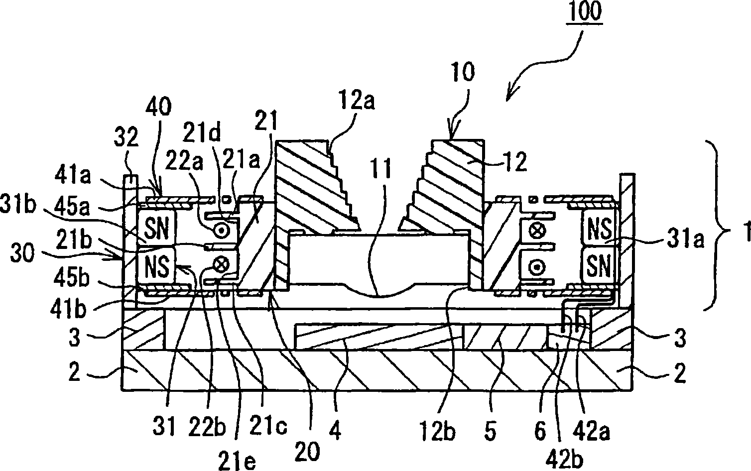
[0063] A camera module according to a first embodiment of the present invention will be described with reference to the drawings. figure 1 It is a sectional view showing the structure of the camera module according to the first embodiment of the present invention.

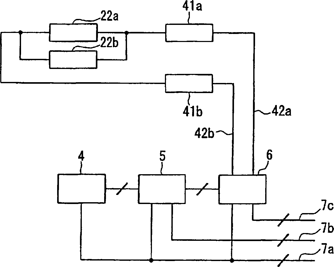
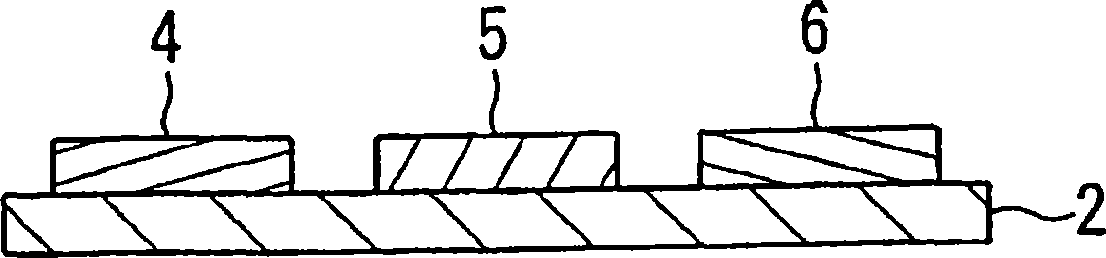
[0064] exist figure 1 Among them, the camera module 100 includes a lens module 1 , a substrate 2 , a support portion 3 , an imaging element 4 , a control element 5 , and a drive element 6 . The lens module 1 includes a lens unit 10 , a movable base 20 , a fixed base 30 , and a connection unit 40 .

[0065] The lens unit 10 has a lens 11 and a lens holder 12 . The lens 11 is formed by injection molding or cutting processing of glass or resin, and functions to bend light. Furthermore, the lens 11 is desirably made of a material with a high refractive index and low dispersion. Furthermore, the lens holder 12 is produced by injection molding or the like using resin or the like. The lens holder 12 is substantially ...

no. 2 approach

[0110]A camera module according to a second embodiment of the present invention will be described with reference to the drawings. 9A is a plan view showing the structure of the lens module according to the second embodiment of the present invention, and FIG. 9B is a cross-sectional view showing the lens module according to the second embodiment of the present invention, Figure 9C It is a bottom view showing the lens module according to the second embodiment of the present invention. Figure 9B is along Figure 9A and Figure 9C The sectional view of the arrow direction of the 9B-9B line.

[0111] Furthermore, the camera module of the second embodiment differs in the structure of the lens module from the camera module of the first embodiment. That is, in the camera module of the second embodiment, the figure 1 In the camera module 100 shown, the lens module 201 of the second embodiment may be used instead of the lens module 1 . For this reason, the camera module according to...

no. 3 approach

[0130]A camera module according to a third embodiment of the present invention will be described with reference to the drawings. 10 is a plan view showing the structure of the upper spring (lower spring) of the camera module according to the third embodiment of the invention.

[0131] The shapes of the upper spring 341a and the lower spring 341b of the camera module according to the third embodiment are the same as those of Figure 7 The camera module according to the first embodiment shown has different upper springs 41a and lower springs 41b. Specifically, the upper spring 41a and the lower spring 41b in the first embodiment have four arms, but the upper spring 341a and the lower spring 341b according to the third embodiment have two arms. Other configurations of the camera module according to the third embodiment are the same as those of the camera module according to the first embodiment. That is, in the camera module of the third embodiment, the figure 1 In the camera ...


PUM


Abstract

A camera module has a lens section (10) including at least one lens (11), an imaging element (4) having a light receiving surface substantially perpendicular to the optical axis direction of the lens (11), a fixed section (30) provided on the outer periphery side of the lens section (10), a first elastic body (41a) provided on the opposite side of the imaging element (4) relative to the lens (11) and connecting the lens section (10) and the fixed section (30), and a second elastic body (41b) provided on the imaging element (4) side relative to the lens (11) and connecting the lens section (10) and the fixed section (30). The first elastic body (41a) and the second elastic body (41b) have the same shape, the first elastic body (41a) and the second elastic body (41b) are arranged so as to be opposed to each other with their center axes aligned, and the second elastic body (41b) is placed such that its shape is different from that shape of the first elastic body (41a) which is projected in the optical axis direction of the lens (11).

Description

technical field [0001] The invention relates to a camera module with small size, thin profile, low power consumption and automatic focusing function. Background technique [0002] As a conventional camera module, there is a camera module having an autofocus function disclosed in Patent Document 1, for example. FIG. 21 is a cross-sectional view showing the structure of a conventional camera module. [0003] In FIG. 21 , a voice coil motor 953 has a drive coil 920 , a coil 922 , a center yoke 923 , and a permanent magnet 924 . A movable base 952 is connected to the coil 922 . The center yoke 923 is provided on a yoke fixing portion 990 a provided on a fixing base 990 . A lens 981 is provided in the opening 990 e of the fixed base 990 , and a lens 982 is also arranged in the opening of the center yoke 923 . [0004] In the camera module 900, a shaft mounting plate 991 is fixed parallel to the yoke fixing portion 990a, and one ends of two guide shafts 951a and 951b extending...

Claims


Application Information

Patent Timeline
IPC IPC(8): G02B7/04G02B7/08G02B7/09H04N5/225G02B7/02
CPCG02B7/04H04N5/2257G02B7/026G02B7/08H04N23/57
Inventor 饭岛友邦玉木悟史春口隆田米正树
Owner PANASONIC INTELLECTUAL PROPERTY CORP OF AMERICA
Why Eureka
Try Eureka