
Three-dimensional measurement system and method of the same, and color-coded mark

A three-dimensional measurement and code technology, applied in photogrammetry/video measurement, measurement point marking, measurement device, etc., can solve problems such as low work efficiency, difficulty in full automation, and difficulty in determining different images, and improve efficiency. , to achieve the effect of automation

Active Publication Date: 2007-02-14
KK TOPCON
View PDF3 Cites 6 Cited by
  • Summary
  • Abstract
  • Description
  • Claims
  • Application Information

AI Technical Summary

Problems solved by technology

[0005]However, if this method is adopted, there are the following problems: different measuring instruments must be used for the measurement of small areas and large areas, it is troublesome, and it is not possible to Fully automate 3D measurement
In this way, even though each operation is simple, the overall operation is troublesome and the operation efficiency is low.
[0006] In addition, in the past signs, because the same figure was used, it was difficult to identify between these signs, it was not easy to determine the corresponding points in the stereoscopic image, and it was not easy to The problem of easily determining the correspondence between different images
Therefore, there is a problem that it is difficult to fully automate the process from imaging to 3D measurement
In addition, when correcting the color of the image, it is necessary to prepare a separate calibration mark that is different from the target plate.

Method used


Image

  • Three-dimensional measurement system and method of the same, and color-coded mark
  • Three-dimensional measurement system and method of the same, and color-coded mark
  • Three-dimensional measurement system and method of the same, and color-coded mark

Examples


no. 1 Embodiment approach

[0066] The invention improves the efficiency of the non-contact three-dimensional measurement and realizes the automation by using the mark (marker) with a code.

[0067] Embodiments of the present invention will be described in detail below with reference to the drawings.

[0068] First, as an example of a coded target, a color coded mark (target) will be described.

[0069] [with color code label]

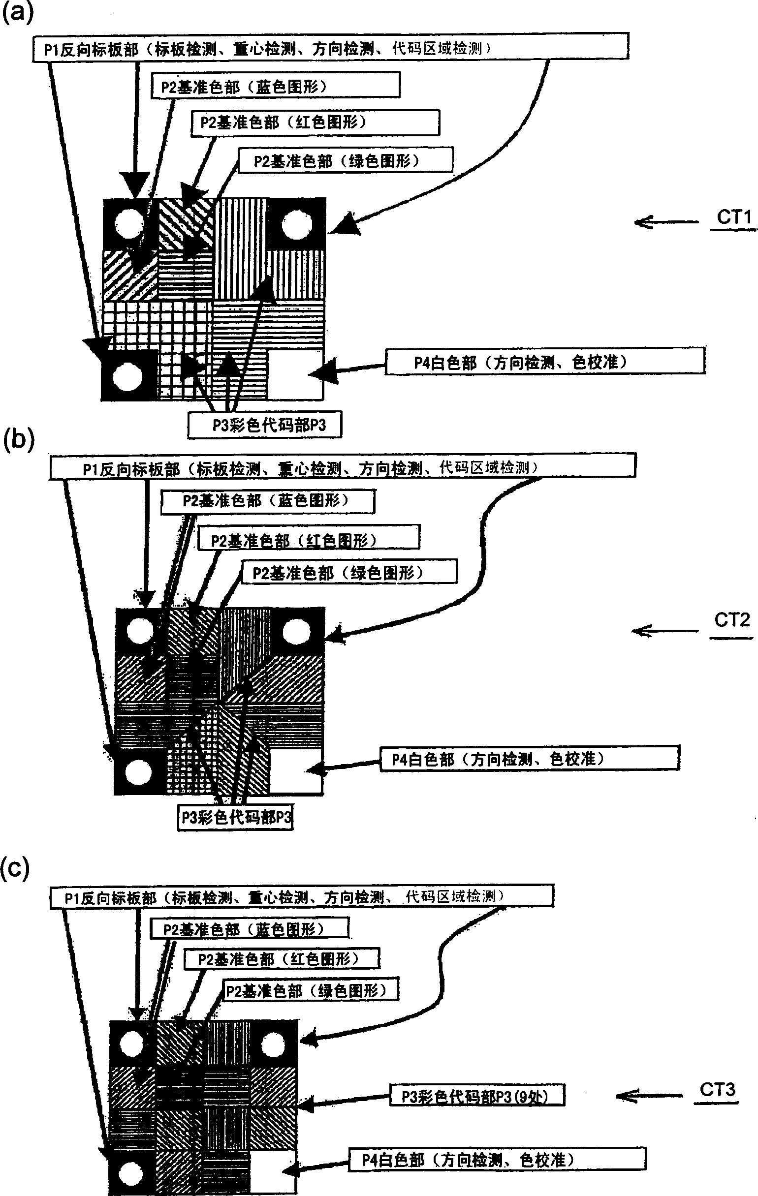
[0070] figure 1 Shown is an example of a color-coded target plate. figure 1 (a) is a color-coded label with three color-coded unit areas, figure 1 (b) is a color-coded label with 6 color-coded unit areas, figure 1 (c) is a color-coded target plate with 9 color-coded unit areas. figure 1 (a)~(c) with color coded target CT (CT1~CT3), consists of position detection pattern (reverse target part) P1, reference color pattern (reference color part) P2, color code pattern (color Code part) P3, empty figure (white part) P4 constitutes.

[0071] The reverse target unit P1 is us...

no. 2 Embodiment approach

[0266] Instead of pasting the color-coded target CT, or in combination with the pasting of the color-coded target CT, the reference pattern may be projected onto the measurement object 1 by the projection device 12 .

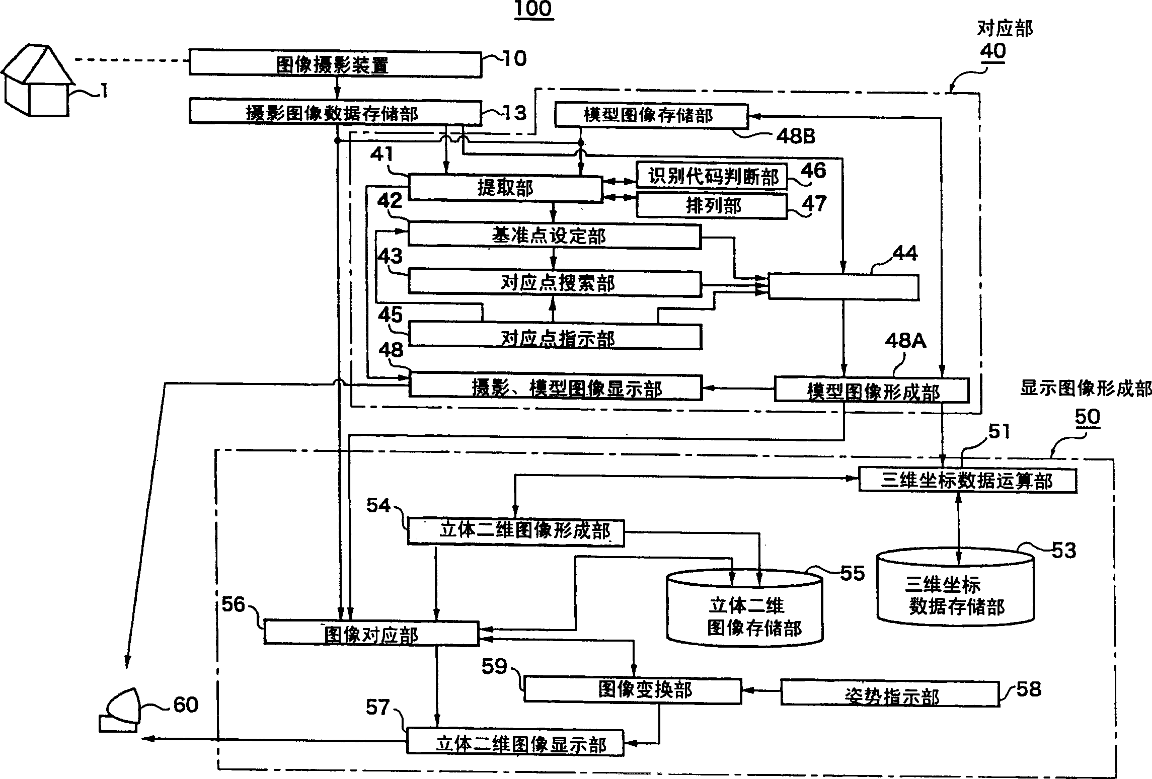
[0267] Figure 23 It is a block diagram of an example of the overall configuration of a three-dimensional measurement system 100A in the second embodiment. with the first embodiment (see figure 2 ) compared with the three-dimensional measurement system 100 in ), the projection device 12 and the calculation processing unit 49 are added, and the other structures are the same as those of the first embodiment. The projection device 12 projects various patterns such as a pattern for position detection onto the object 1 to be measured, and the various projected patterns are photographed by the imaging device 10 for calibration and three-dimensional measurement. The calculation processing unit 49 receives image data, detects various patterns, generates various patte...

no. 3 Embodiment approach

[0282] In this embodiment, an example in which a color reverse target is used as the pattern P1 for position detection will be described.

[0283] In this embodiment, the method of using the colored position detection pattern in (4) is adopted as a search method for target position extraction.

[0284] (4) Different colors are used for the three-cornered reverse targets of the color coded target CT, so that the reflected colors of each reverse target are different. The reverse targets of the 3 corners are made to have different colors, so it is easy to judge each reverse target belonging to one color-coded target. In the reverse target grouping process, when multiple reverse targets are used, reverse targets of different colors are also used to select the closest one, which makes the process easier.

[0285] In the case of using multiple reverse targets as the reference point RF, the reverse target with color-coded CT and a single reverse target are mixed, so the reverse targ...


PUM


Abstract

This invention provides a three-dimensional measurement system that improves the efficiency of and enables the automation of non-contact three-dimensional measurement over a wide range using a coded target. The solving scheme of the invention is that, a measuring object 1 is photographed in stereo such that the resulting images include four coded marks CT each having a position detection pattern P1 and a code pattern P3. A series of images are photographed in stereo such that adjacent images share two coded marks CT. The position detection pattern P1 and the code pattern P3 are extracted from a pair of photographed images. A point corresponding to a reference point is searched for using the identification codes of the coded marks CT. A stereo matching area is determined. All the processes including photographing, extraction, orientation and three-dimensional measurement can be fully automated.

Description

technical field [0001] The invention relates to a three-dimensional measuring system, a three-dimensional measuring method and a color-coded mark. More specifically, it relates to a three-dimensional measurement system and a three-dimensional measurement method capable of automatically measuring a wide range of areas by connecting and integrating various areas for three-dimensional measurement, and relates to a position detection graphic for indicating a measurement position and a Color-coded graphics for identifying markers Color-coded markers for 3D shape determination and measurement. Background technique [0002] In the past, in the case of three-dimensional measurement in a non-contact manner, each small area was measured using a relatively large device called a non-contact three-dimensional measuring instrument that integrates a graphic projector and a CCD camera, and then a camera is used to measure each small area. The measurement method measures various targets (タ一...

Claims


Application Information

Patent Timeline
Patent Type & Authority Applications(China)
IPC IPC(8): G01B11/00G01C11/00
CPCG01C11/06G06K9/3216G01C15/02G06K2009/3225G06V10/245
Inventor 高地伸夫森山拓哉秀岛昌行山田光晴
Owner KK TOPCON
Learn More