System and method of real-time monitoring for monoboard clock signal

A clock signal, real-time monitoring technology, applied in the field of communication, can solve problems such as inability to detect, limit the scope of application, and inability to realize automatic detection, and achieve the effect of improving reliability

Inactive Publication Date: 2010-05-12
HUAWEI TECH CO LTD
View PDF3 Cites 1 Cited by
  • Summary
  • Abstract
  • Description
  • Claims
  • Application Information

AI Technical Summary

Problems solved by technology

However, using a special frequency tester to obtain the clock signal of the board also has disadvantages: first, using an additional frequency tester requires money to purchase the instrument; second, this method can only be used in the development and debugging stages of the board, After the boards are mass-produced and processed, it is difficult to test and monitor a large number of boards, and after the boards are sold, it is also difficult to use a special frequency tester to test the boards due to the lack of necessary debugging environment at the user's site. Test monitoring; thirdly, this method requires manual operation. Although the special test tools are rich in functions, they need to be operated by familiar developers, which greatly limits the scope of application of this test method, and because Automatic detection cannot be realized, and the control system of the single board cannot grasp its own running state, and cannot realize self-state monitoring
[0007] First, it is necessary to use a dedicated clock signal to test the chip, which increases the cost of circuit design, and the circuit design will be limited by the requirements of the dedicated chip. For example, the circuit of the main control module must be connected according to the requirements of the chip. specifications, etc.;
[0008] Second, the number of clock signals tested by the clock signal test chip is limited, and the number of detectable clock signals is affected by the selected clock signal test chip. If it exceeds the number of testable clock signals of the clock signal test chip, it cannot be detected;
[0009] Third, it is impossible to upgrade the clock signal detection circuit

Method used


Image

  • System and method of real-time monitoring for monoboard clock signal
  • System and method of real-time monitoring for monoboard clock signal
  • System and method of real-time monitoring for monoboard clock signal

Examples


Embodiment Construction

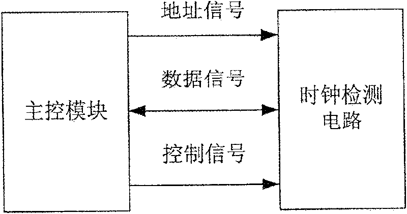
[0049] In the present invention, a clock signal detection module is added to the single board, and the clock signal detection module is realized by a logic code module, and is connected with the main control module of the single board to realize real-time monitoring of the clock signal of the single board.

[0050] The technical solution of the present invention will be further described below through the embodiments in conjunction with the accompanying drawings.

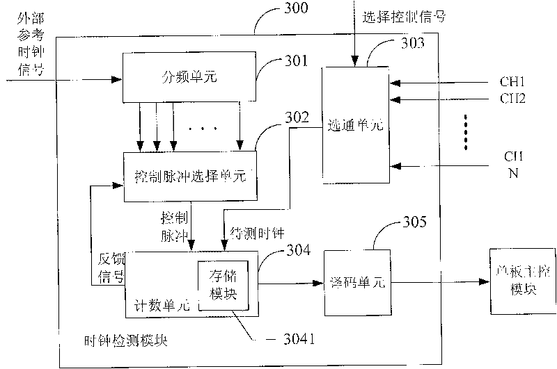
[0051] Such as image 3 As shown, it is an embodiment of a system for real-time monitoring of a board clock signal in the present invention, the system includes a clock signal detection module 300, and the clock signal detection module 300 includes a frequency division unit 301, a control pulse selection unit 302, A gating unit 303, a counting unit 304 and a decoding unit 305;

[0052]The frequency division unit 301 receives an external reference clock signal, and divides the external reference clock signal into cl...


PUM


Abstract

This invention provides a system for monitoring single-board clock signals in real time including a clock signal test module and a single-board primary control module, in which, said clock signal testmodule carries out counting operation to being tested clock signals in the effective clock width of the control pulse to get the counting information and codes it to get the clock signal frequency information, said single-board primary module receives said clock signal frequency information and judges if it is normal. This invention also provides a monitor method including: A, receiving control pulses to carry out counting operation to being tested clock signal in the effective time width to get the counting information, B, coding said counting information to get the frequency information ofsaid clock signal, C, judging if the information is normal.

Description

technical field [0001] The invention relates to the communication field, in particular to a system and method for real-time monitoring of a clock signal of a single board. Background technique [0002] At present, in the process of designing single boards in the industry, the status monitoring function of single boards has been paid more and more attention. How to monitor the various states in the operation of the hardware system more comprehensively and efficiently has become the key to ensure the stable operation of the hardware modules and realize the working status of the entire hardware system. An important prerequisite for predictability. There are many types of sensor devices that can be used for board status monitoring, but the main monitoring objects focus on characteristics such as temperature, voltage, and current, and there are few sensor devices that can be dedicated to monitor the status of board clock signals. At the same time, as the speed of the system beco...

Claims


Application Information

Patent Timeline
Patent Type & Authority Patents(China)
IPC IPC(8): H04M3/24H04L12/26
Inventor 马黎
Owner HUAWEI TECH CO LTD
Why Eureka
Try Eureka