Heat pipe receiver in intermediate temperature in use for generating electricity from solar heat
A solar thermal power generation and receiver technology, which is applied to solar thermal power generation, solar thermal collectors, solar thermal collectors using working fluid, etc. Solar radiation absorption and other issues, to achieve the effect of increasing service life, saving manufacturing costs, and improving heat transfer effect
- Summary
- Abstract
- Description
- Claims
- Application Information
AI Technical Summary
Problems solved by technology
Method used
Image

Examples
Embodiment 1
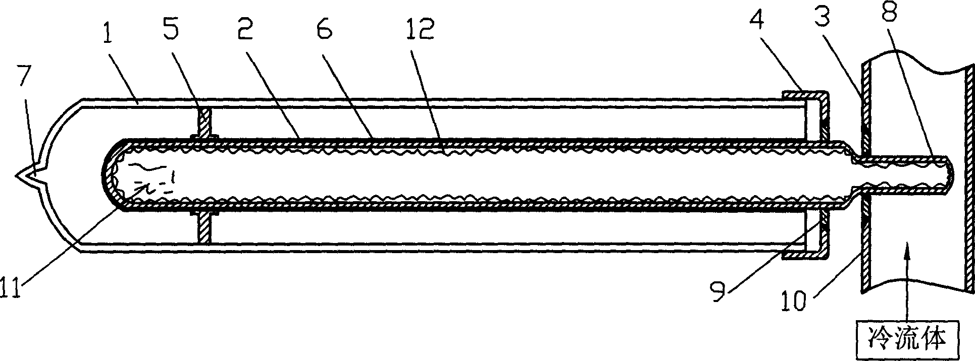
[0027] The specific structure of the medium temperature heat pipe receiver for solar thermal power generation in this embodiment is as follows figure 2 As shown, it includes a glass sleeve 1 and a cooling fluid channel 3. The glass sleeve 1 is closed at one end and open at the other end, and also includes a medium-temperature heat-absorbing heat pipe 2. The medium-temperature heat-absorbing heat pipe 2 is inserted into the glass sleeve 1. The medium-temperature heat-absorbing heat pipe 2 Made of metal (carbon steel below 450°C, heat-resistant steel or low alloy steel above 450°C). The part of the medium-temperature heat-absorbing heat pipe 2 exposed to the glass sleeve 1 gradually shrinks into a smaller-diameter condensation section 8, the condensation section 8 is located in the cooling fluid passage 3, and is sealed with the cooling fluid passage 3, the medium-temperature heat-absorbing heat pipe 2 and the glass sleeve The open ends of the tubes 1 are sealed and connected b...
Embodiment 2
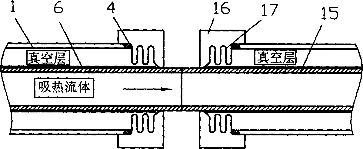
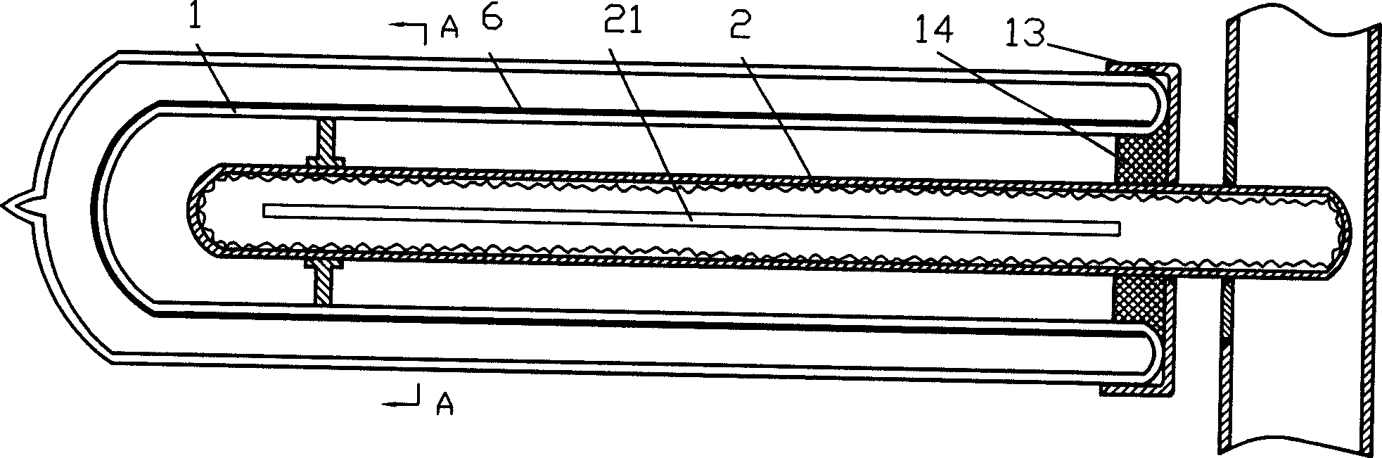
[0031] The specific structure of the medium temperature heat pipe receiver for solar thermal power generation in this embodiment is as follows image 3 as shown, Figure 4 for image 3 The A-A section diagram. The glass sleeve 1 of this embodiment is a double-layer glass sleeve, with a vacuum layer between the two layers of glass, and the outer surface of the part of the medium-temperature heat-absorbing heat pipe 2 located in the glass sleeve 1 is covered with a high-temperature-resistant selective absorption coating 6 . The closed end of the glass sleeve 1 is provided with a vacuum sealing tube 7 on the outer glass, which is used to evacuate the middle of the two layers of glass into a vacuum layer. Heat conduction fins 21 are also welded on the medium-temperature heat-absorbing heat pipe 2 , and a thermal insulation cap 13 and a filler 14 are provided at the sealed connection between the medium-temperature heat-absorbing heat pipe 2 and the open end of the glass sleeve 1...
Embodiment 3
[0034] The specific structure of the medium temperature heat pipe receiver for solar thermal power generation in this embodiment is as follows Figure 5 As shown, the glass sleeve 1 of this embodiment is a double-layer glass sleeve, with a vacuum layer between the two layers of glass, and the surface of the inner tube of the double-layer glass sleeve is covered with a high-temperature-resistant selective absorption coating 6 . The closed end of the glass sleeve 1 is provided with a vacuum sealing tube 7 on the outer glass, which is used to evacuate the middle of the two layers of glass into a vacuum layer. Heat conduction fins 21 are also welded on the medium-temperature heat-absorbing heat pipe 2 , and a thermal insulation cap 13 and a filler 14 are provided at the sealed connection between the medium-temperature heat-absorbing heat pipe 2 and the open end of the glass sleeve 1 . Other structures of this embodiment are the same as those of Embodiment 1.
[0035] Working proc...
PUM
 Abstract
Description
Claims
Application Information
 - R&D
- Intellectual Property
- Life Sciences
- Materials
- Tech Scout
- Unparalleled Data Quality
- Higher Quality Content
- 60% Fewer Hallucinations
Browse by: Latest US Patents, China's latest patents, Technical Efficacy Thesaurus, Application Domain, Technology Topic, Popular Technical Reports.
© 2025 PatSnap. All rights reserved.Legal|Privacy policy|Modern Slavery Act Transparency Statement|Sitemap|About US| Contact US: help@patsnap.com