Microwave sulfur lamp with rised energy coupled field intensity

A technology of energy coupling and microwave, applied in the direction of discharge lamps, electrical components, circuits, etc., can solve the problem of low energy coupling efficiency and achieve the effect of enhancing light efficiency

Inactive Publication Date: 2007-02-21
LG ELECTRONICS (TIANJIN) APPLIANCES CO LTD
View PDF0 Cites 2 Cited by
  • Summary
  • Abstract
  • Description
  • Claims
  • Application Information

AI Technical Summary

Problems solved by technology

[0004] In order to solve the problems in the above-mentioned technologies, the purpose of the present invention is to solve the problem of low energy coupling efficiency in the prior art, and change the shape of the bulb into a shape consistent with the internal field strength distribution of the grille, absorbing as much microwave energy as possible , enhance the luminous efficiency

Method used


Image

  • Microwave sulfur lamp with rised energy coupled field intensity
  • Microwave sulfur lamp with rised energy coupled field intensity
  • Microwave sulfur lamp with rised energy coupled field intensity

Examples


Embodiment Construction

[0016] The microwave sulfur lamp with improved energy coupling field strength of the present invention will be described with reference to the accompanying drawings and embodiments.

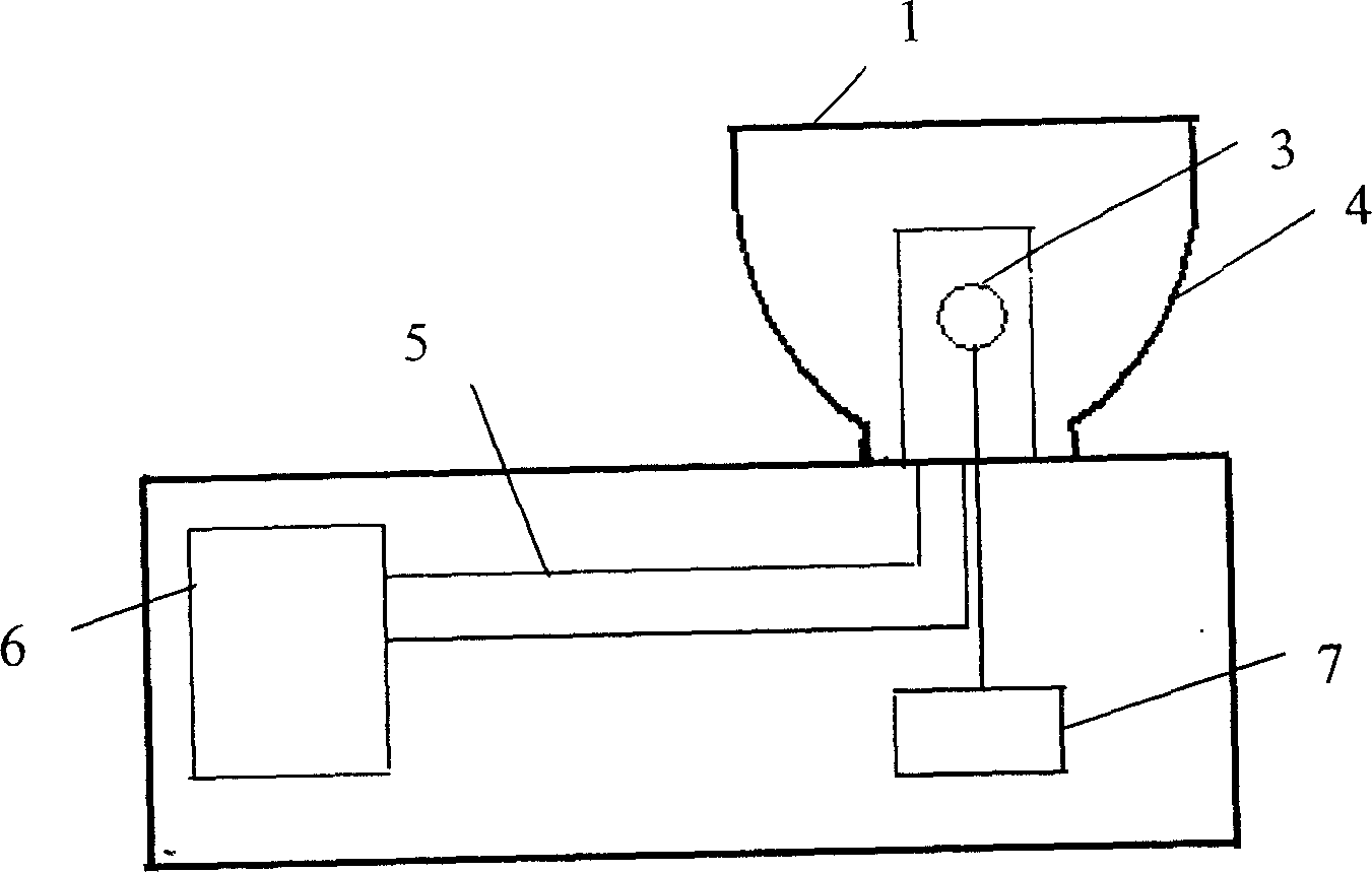
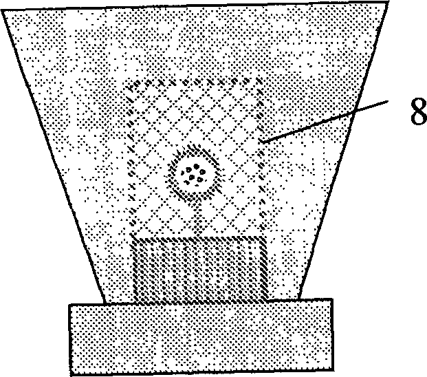
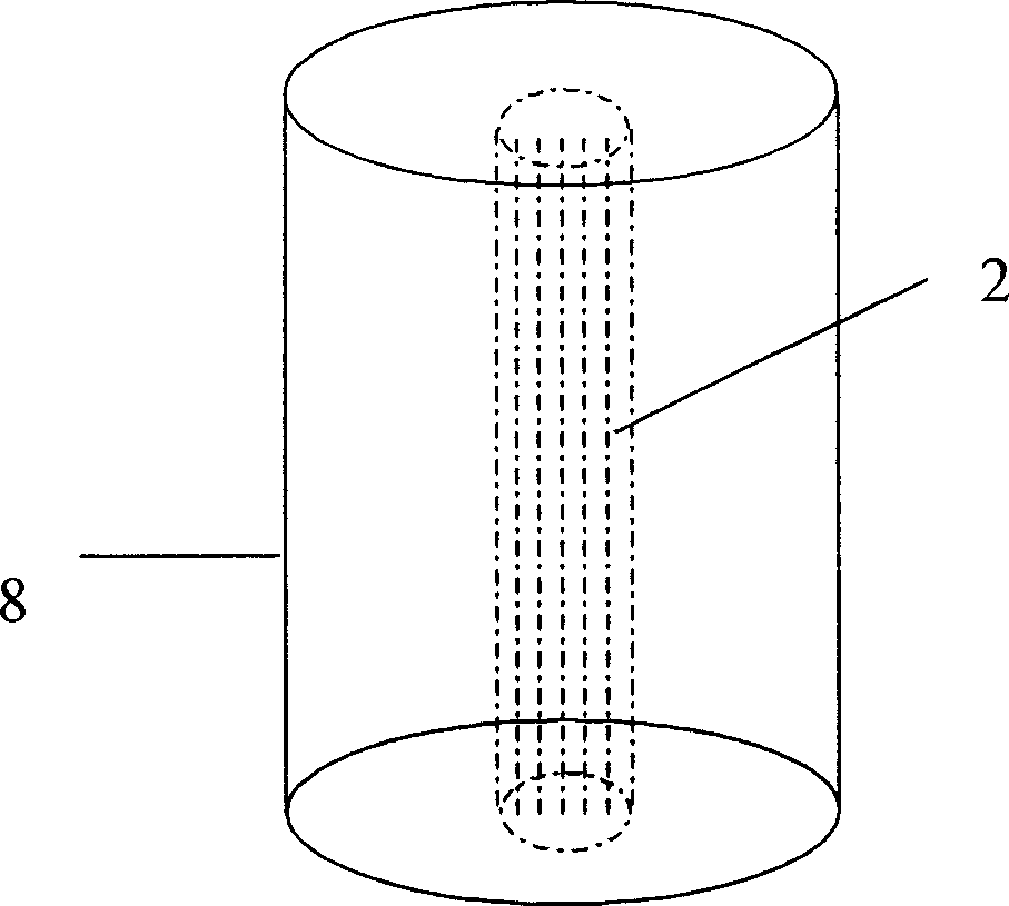
[0017] The structure of the microwave sulfur lamp for improving the energy coupling field strength of the present invention includes a magnetron 6 that emits microwaves, a quartz bulb 2, a mesh cover 8 sleeved outside the quartz bulb 2, and the shape of the quartz bulb 2 It has a cylindrical shape and is on the same axis as the mesh cover 8 so that the field strength of the microwave energy coupling from the magnetron 6 is distributed on the coaxial line of the mesh cover 8.

[0018] The working principle of the system is as follows: the magnetron generates microwaves driven by DC high voltage, and transmits them to the resonant cavity through the wave guide. The microwaves are coupled with the sulfur plasma contained in the quartz bulb in the resonant cavity to excite sulfur molecular radiation. In ...


PUM


Abstract

Microwave sulfur lamp includes microwave source of transmitting out microwave, bulb shell made from quartz, and mesh cover sheathed outside the bulb shell. Outline of the quartz bulb is columned, and the bulb is on the same axis of the said mesh cover. Thus, field intensity coupled from energy of microwave sent from microwave source is distributed on coaxial line of the mesh cover. Outline of the bulb is consistent to outline of inner distribution of field intensity so as to absorb energy of microwave as more as possible. The invention enhances capability of lamp to absorb energy coupled to microwave so as to raise use ratio of energy and increase optical efficiency.

Description

Technical field [0001] The invention relates to a microwave sulfur lamp which improves the energy coupling field strength. Background technique [0002] figure 1 It is the original microwave sulfur lamp system device and schematic diagram. The general working principle of the microwave sulfur lamp system is that the magnetron 6 in the microwave sulfur lamp generates microwaves under DC high voltage drive, and transmits them to the resonant cavity through the waveguide 5, and the microwaves are in resonance. The cavity is coupled with the sulfur plasma contained in the quartz bulb 6 to excite sulfur molecules for radiation. In order to make the plasma work uniformly and stably, the quartz bulb 6 is driven by the motor 7 to rotate at a high speed. [0003] The field strength distribution of the microwave energy coupling is on the coaxial line of the mesh cover 8, but the quartz bulb 6 is at its geometric center, and the energy utilization rate is not high, resulting in low light ...

Claims


Application Information

Patent Timeline
IPC IPC(8): H01J65/00
Inventor 李元鹤张涛
Owner LG ELECTRONICS (TIANJIN) APPLIANCES CO LTD
Why Eureka
Try Eureka