Voltage boosting type device and method of consecutive correcting power factor in average electric current control mode

A technology of power factor correction and average current control, applied to output power conversion devices, control/regulation systems, electrical components, etc.

Inactive Publication Date: 2007-02-21
NIKO SEMICON
View PDF0 Cites 29 Cited by
  • Summary
  • Abstract
  • Description
  • Claims
  • Application Information

AI Technical Summary

Problems solved by technology

[0010] The technical problem to be solved by the present invention is to provide a power factor correction device with simple circuit, easy integration and high power factor and low distortion, so as to make up for the shortcomings in the prior art

Method used


Image

  • Voltage boosting type device and method of consecutive correcting power factor in average electric current control mode
  • Voltage boosting type device and method of consecutive correcting power factor in average electric current control mode
  • Voltage boosting type device and method of consecutive correcting power factor in average electric current control mode

Examples


Embodiment Construction

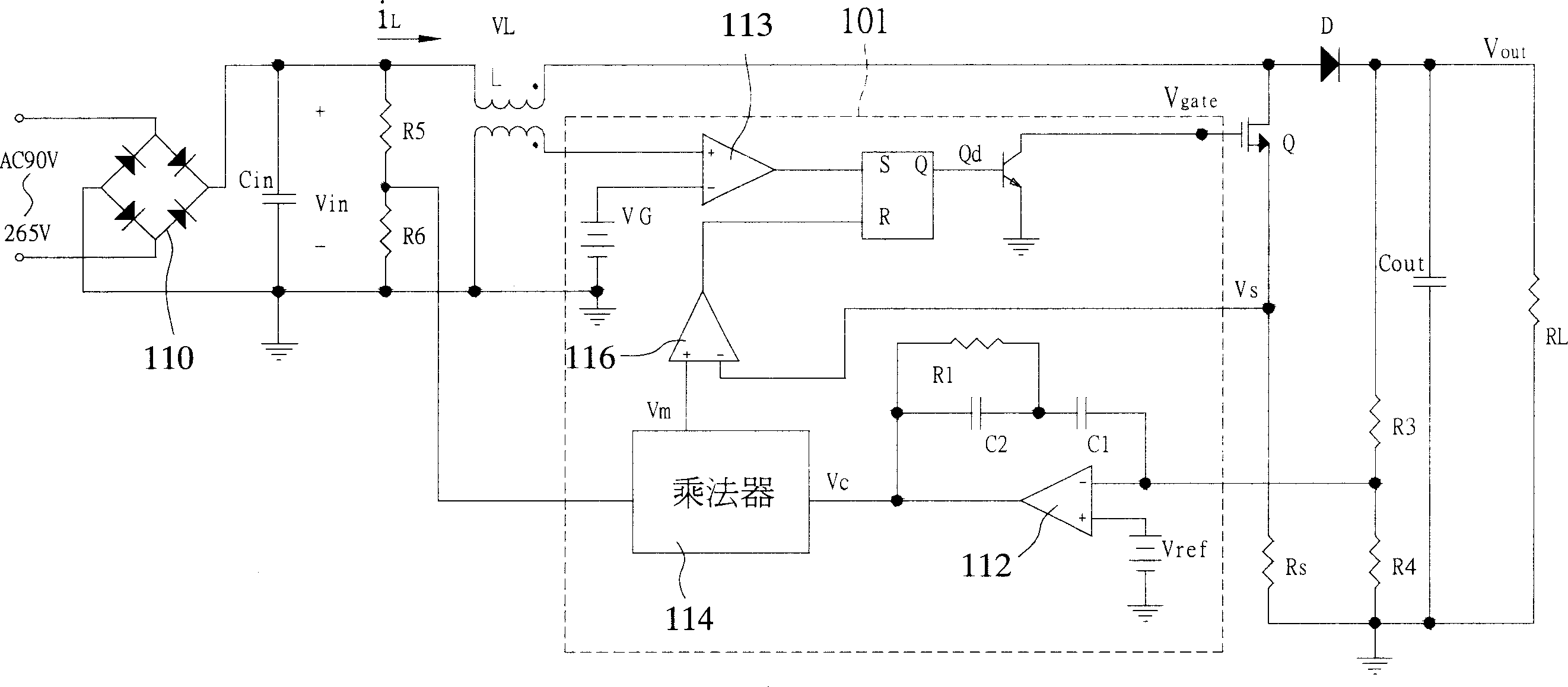
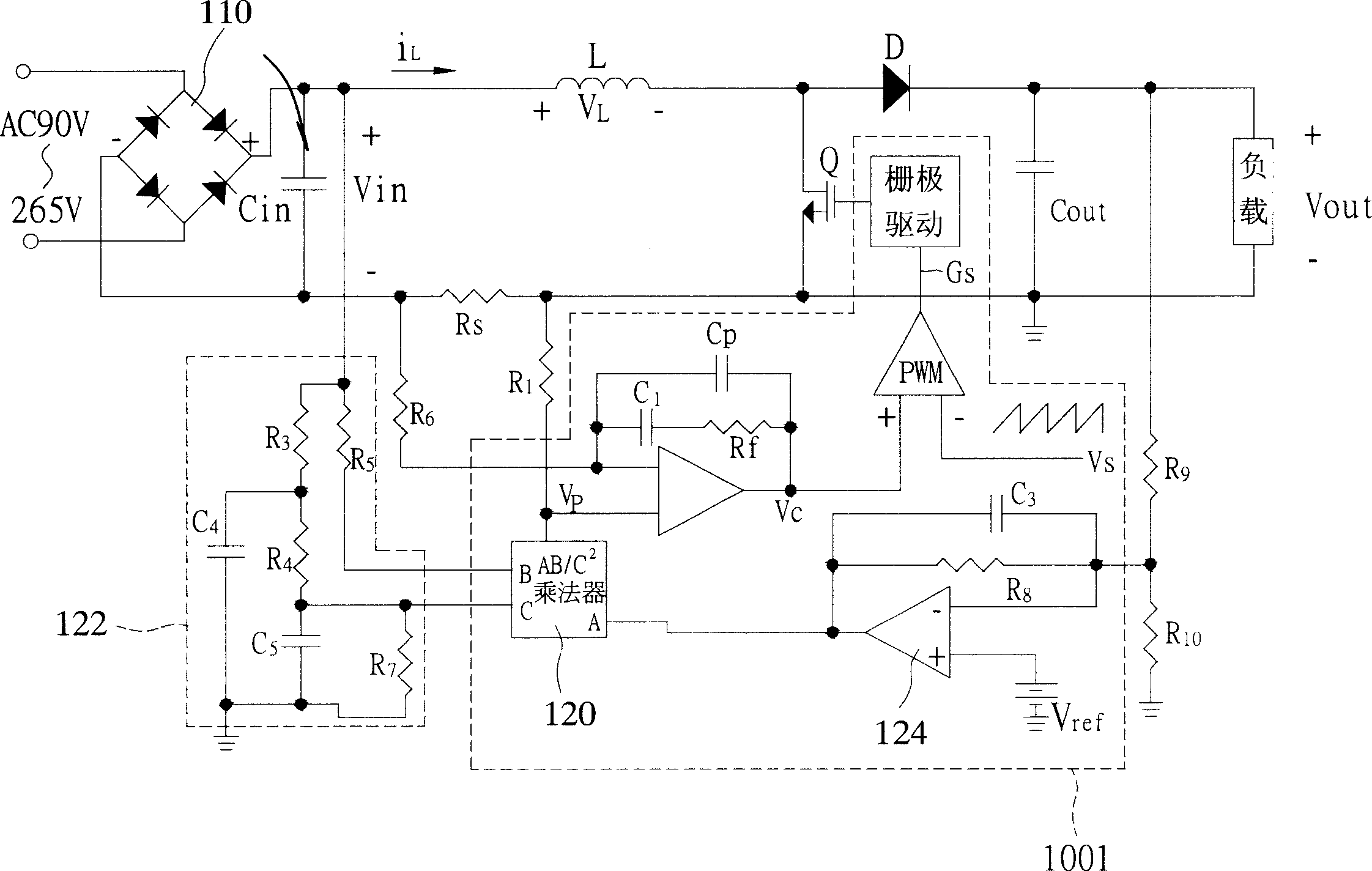
[0051] see Figure 5 , is a schematic diagram of the structure of the first preferred AC / DC power converter used in the present invention. The step-up continuous power factor correction device 1 in the average current control mode of the present invention controls the input by controlling the periodic switching action of a switch Q. Current I in Then control the input voltage V rectified by the rectifier device BD in , so that the input current I of the AC / DC power converter in with input voltage V in It is proportional and in phase, and can obtain high power factor and low total harmonic distortion (Total Harmonic Distortion; THD).

[0052] please cooperate Figure 5 refer to Figure 6 , which is a schematic circuit block diagram of the first embodiment of the present invention. The step-up continuous power factor correction device 1 of the average current control mode of the present invention is applied in the AC / DC power converter, and is used to control the switching...


PUM


Abstract

Using resetable integrator carries out integral conformity calculation for voltage signal of output difference of voltage error amplifier, and input current signal obtained from sensor respectively. Then, using comparison operation controls work cycle of switch to make input current and input voltage in AC / DC power converter in proportion and in same phase. Comparing with traditional PFC circuit, the disclosed control mode uses fewer parts and is simpler. The disclosed device is easier to be integrated to packaging body with fewer pins as well as can obtain high power factor and low total harmonic distortion.

Description

technical field [0001] The present invention relates to a step-up continuous power factor correction device in the average current control mode, in particular to a single-cycle control technology to achieve high power factor and low total harmonic distortion (Total Harmonic Distortion; THD) of the power system. ) power factor correction device and method. Background technique [0002] High-quality power supply has always been the goal pursued by countries all over the world. However, building a large number of power plants is not the only way to solve the problem. On the one hand, increasing the energy of power supply and on the other hand, improving the power factor or efficiency of electrical products can effectively solve the problem. question. [0003] The main function of the power factor corrector (PFC) is to make the phase of the input voltage and the input current of the electrical product the same, and make the load of the electrical product similar to a resistive ...

Claims


Application Information

Patent Timeline
Patent Type & Authority Applications(China)
IPC IPC(8): H02M1/14G05F1/613
CPCY02P80/10
Inventor 吴俊政黄勤朱宁张新
Owner NIKO SEMICON
Why Eureka
Try Eureka