

Eight slanting rollers shape structure of rolling mill of eight slanting rollers
A rolling mill and roll shape technology, applied in the direction of metal rolling stand, metal rolling mill stand, roll, etc., can solve the problems affecting the normal operation and jumping of partial eight-high rolling mill
- Summary
- Abstract
- Description
- Claims
- Application Information
AI Technical Summary
Problems solved by technology
Method used
Image

Examples
Embodiment Construction
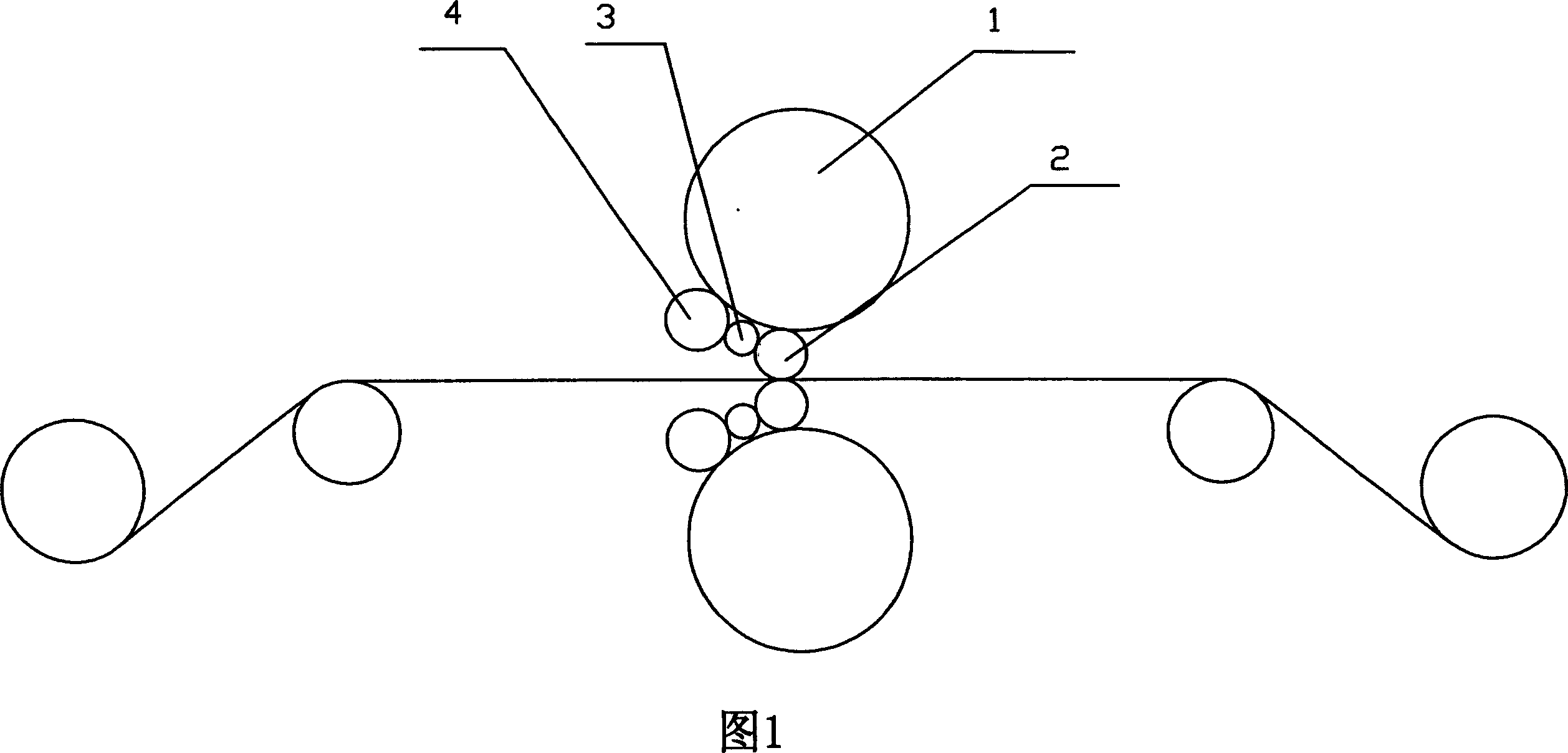
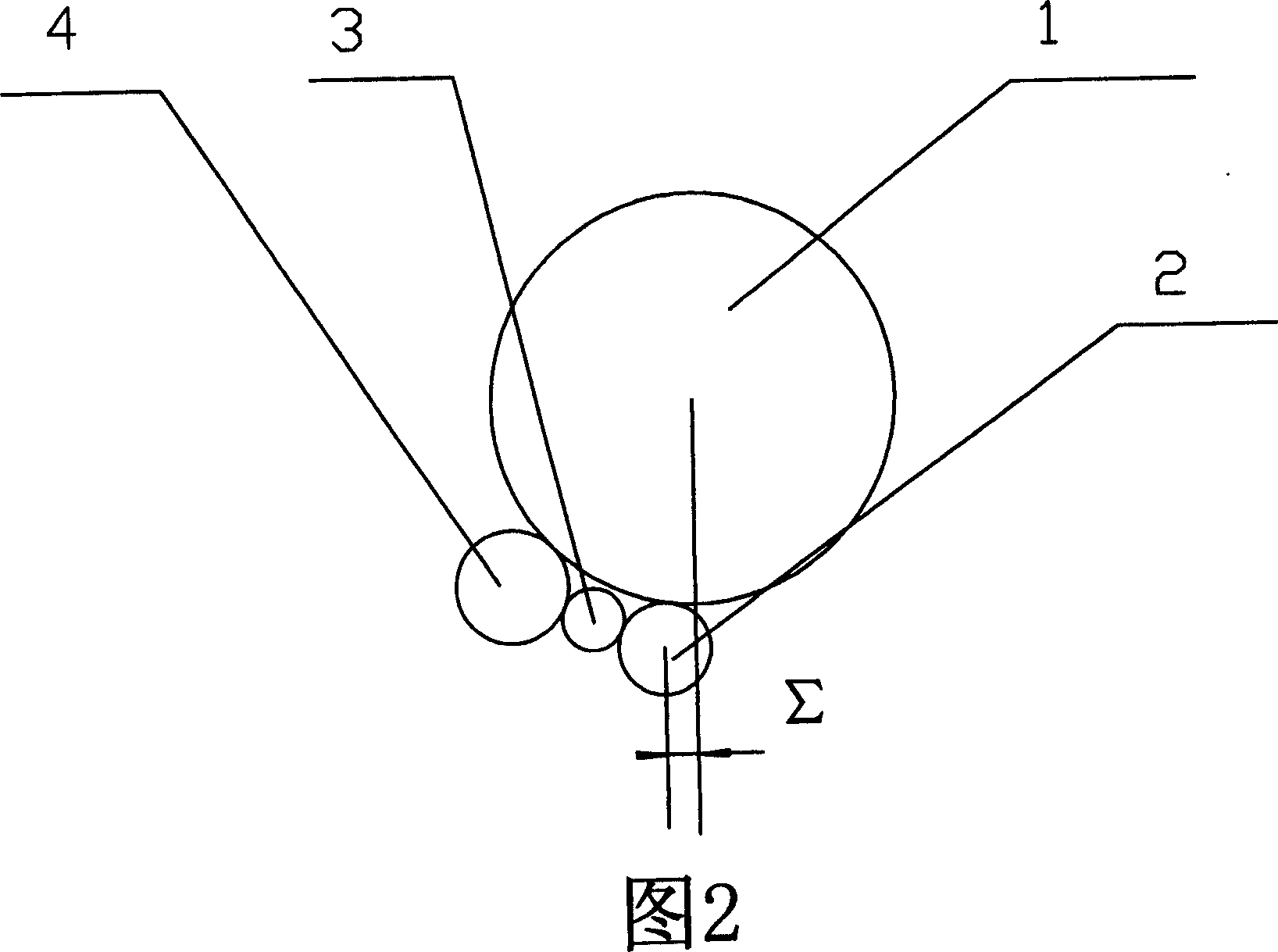
[0023] Now in conjunction with accompanying drawing and embodiment the present invention is described in further detail:
[0024] As shown in the figure, the present invention includes upper and lower support rolls 1, upper and lower work rolls 2 located between the upper and lower support rolls 1, upper and lower intermediate rolls 3, and upper and lower support rolls 4, and the upper and lower work rolls 2 and the upper and lower support rolls 4 are close to the upper and lower Inside the back-up roll 1, the middle roll 3 is located between the work roll 2 and the side back-up roll 4 and is close to them. The center of the work roll 2 deviates from the centerline of the back-up roll 1 toward the side back-up roll 4. The special feature is that The offset from the center line of the backup roll 1 from the center of the work roll 2 to the side support roll 4 is 6%-8% of the diameter of the backup roll 1, the work roll 2, the backup roll 1, the side backup roll 4, the middle rol...
PUM
 Abstract
Description
Claims
Application Information