External housing safety device for turbocharger with axial flow fluid compressor

A technology of compressors and turbines, applied in the field of shell inserts, can solve the problems of high cost and trouble

Inactive Publication Date: 2007-02-28
MAN ENERGY SOLUTIONS SA
View PDF1 Cites 12 Cited by
  • Summary
  • Abstract
  • Description
  • Claims
  • Application Information

AI Technical Summary

Problems solved by technology

[0005] However, in the case of a turbine according to EP 1 233 190 A1, a complex and expe

Method used


Image

  • External housing safety device for turbocharger with axial flow fluid compressor
  • External housing safety device for turbocharger with axial flow fluid compressor
  • External housing safety device for turbocharger with axial flow fluid compressor

Examples


Embodiment Construction

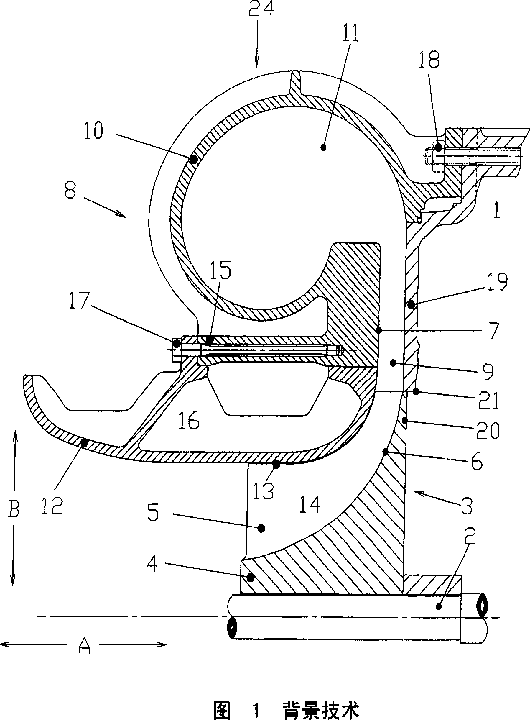
[0025] Fig. 1 shows a partial longitudinal sectional view of a centrifugal compressor in the background art. The exhaust gas turbocharger in this figure has a shaft 2 supported in a bearing housing 1 in its central longitudinal region, which supports a turbine and a turbine, not shown here, on its end protruding from the support bearing. A compressor wheel 3 through which fluid flows radially is shown schematically in the figure.

[0026] The compressor wheel 3 shown has a hub 4 mounted non-rotatably on a shaft 2 driven by a turbine, which hub has radially protruding blades 5 on the circumferential side. The outer contour 6 of the hub 4 and the inner contour 7 of the compressor housing 8 form a fluid channel 9 which narrows outwards from the axial direction A into the radial direction B, the cross section of which corresponds to the contour of the blades 5 . The compressor casing 8 is fixed to the bearing housing 1 by means of a rigid fixing device 18 . From the fluid inlet ...


PUM


Abstract

The invention relates to a turbomachine with a compressor wheel (3) through which fluid flows radially. The compressor housing (8) consists of an outer spiral housing (10) and an inner housing insert (12). The compressor wheel (3) may break due to aging. Ideally the breakout should be caught by the casing insert (12) in order to secure the casing of the turbine. Taking into account the force of the shock release due to the breaking part of the compressor wheel (3), the invention proposes a special construction, in particular of the housing inner insert (12) as a spare part, so that the breaking part can be Reliable and cost-effective retention in the turbine, that is to say keeping the casing of the turbine secure.

Description

technical field [0001] The invention relates to a turbomachine with a compressor wheel through which fluid flows radially and to a housing insert for installation in the turbomachine. Background technique [0002] The basic construction and principle of operation of such a turbomachine, for example a centrifugal compressor such as a turbocompressor, is known per se and will therefore not be described in detail here. EP 1 233190 A1 discloses a turbomachine with a compressor wheel through which the fluid flows radially. [0003] After prolonged operation under unfavorable operating conditions, the compressor wheel of such a turbine is so weakened by corrosion, erosion and aging that rupture of the compressor wheel cannot be avoided. If the compressor wheel breaks, at which point the wheel breaks into at least two or three large pieces, these parts are thrown outwards due to the high centrifugal force. In this case broken parts may fly out of the compressor housing. At the s...

Claims


Application Information

Patent Timeline
IPC IPC(8): F04D29/42F04D29/62
CPCF04D29/624F04D29/4213F01D21/045Y02T50/60F04D29/28F04D29/42F04D29/44
Inventor T·温特D·武特茨
Owner MAN ENERGY SOLUTIONS SA
Why Eureka
Try Eureka