Hydraulic brake mechanism and vacuum auxiliary brake device

A technology of hydraulic braking and vacuum boosting, which is applied in the direction of hydraulic braking transmission devices, etc., to achieve the effects of reducing the labor intensity of the driver, enhancing sensitivity, and easy operation

Inactive Publication Date: 2007-03-07
SHANGHAI PORT MACHINERY HEAVY IND
View PDF0 Cites 7 Cited by
  • Summary
  • Abstract
  • Description
  • Claims
  • Application Information

AI Technical Summary

Problems solved by technology

[0005] The purpose of the present invention is to provide a new type of hydraulic brake mechanism with a vacuum booster brake system, which can achieve power boost through the pressure difference between vacuum and atmospheric pressure. At the same time, because the vacuum is not affected by temperature changes, the invention can solve the problem of problem of use

Method used


Image

  • Hydraulic brake mechanism and vacuum auxiliary brake device

Examples


Embodiment Construction

[0022] The technical solutions of the present invention will be further described below in conjunction with the accompanying drawings and embodiments.

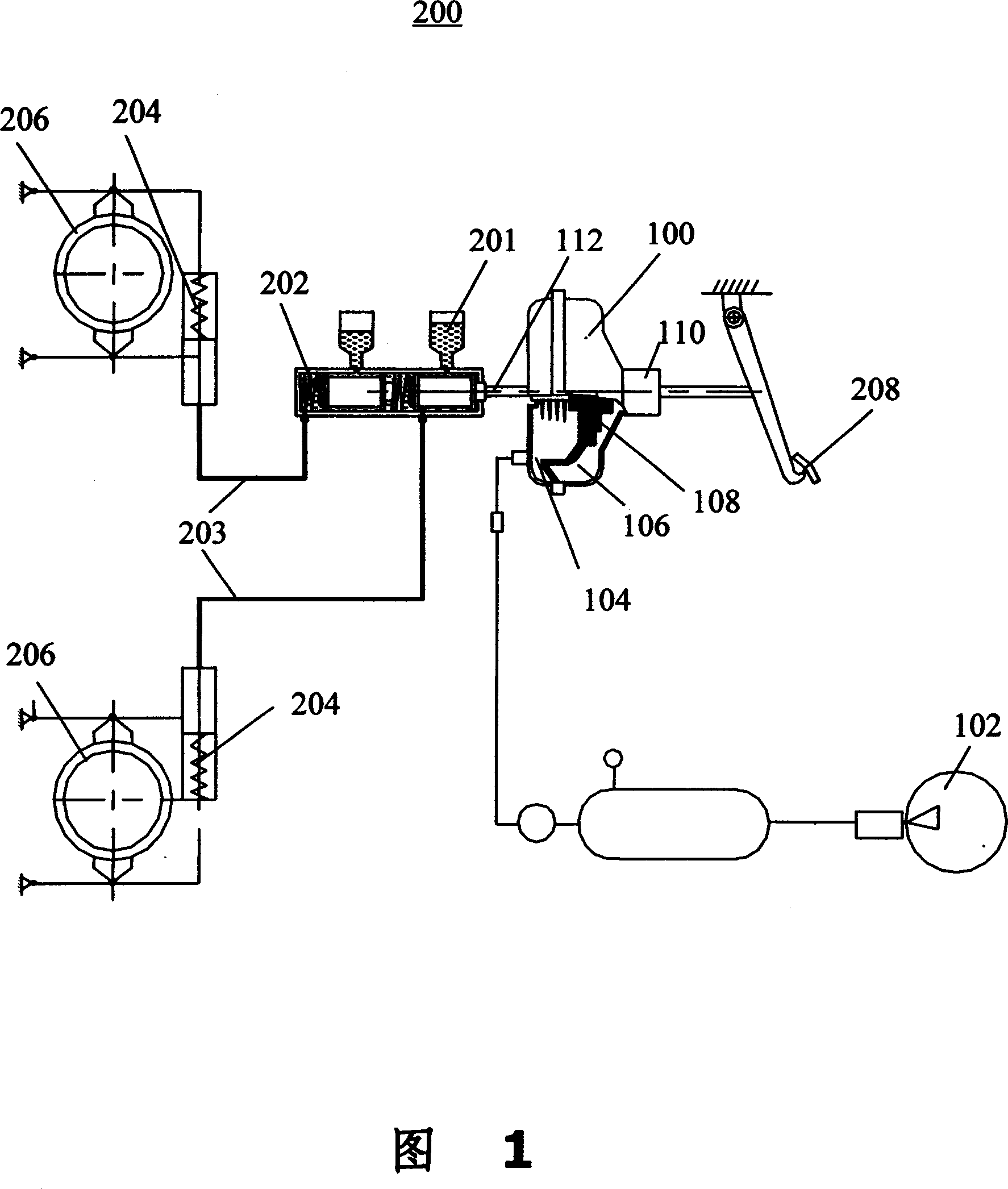
[0023] First, the present invention provides a vacuum booster braking system for a hydraulic braking mechanism. Referring to FIG. 1, FIG. 1 is a structural diagram of a hydraulic braking mechanism and its vacuum boosting braking system according to an embodiment of the present invention. The right part is exactly the structural diagram of the vacuum booster brake system according to the present invention.

[0024] The vacuum booster brake system of the present invention is connected between the pedal of the hydraulic brake mechanism and the brake master cylinder, including:

[0025] Vacuum generating device 102, generating vacuum;

[0026] The vacuum chamber 104 is connected to the vacuum generating device 102, and the vacuum generating device 102 creates a vacuum in the vacuum chamber 104;

[0027] Atmospheric chamber 106 i...


PUM


Abstract

This invention reveals a vacuum boosting braking system for hydraulic braking mechanism by connecting between the mechanism's pedal and the master cylinder, and it comprises of a vacuum generating device, vacuum cavity to which the vacuum generating device connected and in which the vacuum is generated; ether cavity, adjacent to the vacuum cavity through an isolating mechanism whose location could be changed in accordance with the pressure variation in vacuum cavity and ether cavity, which connected to the outside world through a valve that is controlled by the pedal; the handspike, whose one ended connected to the isolating mechanism and the other end to the master cylinder, and the changing location of the isolating mechanism drives the handspike to push the master cylinder; the original pressure of the ether cavity is the same with that of the vacuum cavity, and the stepping on the pedal opens the valve which makes the same pressure inside the ether cavity and barometric pressure, meanwhile, the pressure difference of the ether cavity and the vacuum cavity pushes the isolating mechanism to change locations and to achieve the braking by pushing the braking pump.

Description

technical field [0001] The present invention relates to the field of brake devices, more specifically, to heavy machinery, such as a hydraulic brake mechanism of a crane and a vacuum booster brake system thereof. Background technique [0002] Heavy machinery, such as the braking system of the rotating mechanism of the portal crane used in ports and shipyards, mostly adopts a normally open foot pedal oil circuit braking control system. Slight, so it is widely used in domestically produced gantry cranes. However, in this braking system, the driver depresses the brake pedal to push the piston of the brake master cylinder, and the oil pressure is established in the brake master cylinder, so that a certain pressure is generated in the brake oil circuit, and the brake cylinder is pushed to brake. The dynamic cylinder then pushes the upper end of the brake arm of the brake to stretch outwards for braking, so the braking torque is directly related to the pedaling force. If the brak...

Claims


Application Information

Patent Timeline
Patent Type & Authority Applications(China)
IPC IPC(8): B60T13/565
Inventor 钟华陈杏珠
Owner SHANGHAI PORT MACHINERY HEAVY IND
Why Eureka
Try Eureka