Crank lubricating filtering device

A technology of filtering device and lubricating oil, which is applied in the installation/connection of lubricant purification device, lubricating parts, pressure lubricant, etc., can solve the problem of increasing the filtering capacity of the filter 4, the poor universality of the filter 4, and the limitation of and other problems, to achieve the effect of increasing the filtration volume, improving the wide applicability, and improving the lubrication function.

Active Publication Date: 2011-01-26
KYMCO
View PDF0 Cites 0 Cited by
  • Summary
  • Abstract
  • Description
  • Claims
  • Application Information

AI Technical Summary

Problems solved by technology

[0005] Although the conventional filter 4 can filter lubricating oil, because the conventional filter 4 mainly press-fits a metal plate body 41 on the counterweight 21 of the crankshaft 2, and the counterweight of the crankshaft 2 The surface of the block 21 also needs to be provided with a matching groove 211, so the volume of the filter 4 is limited by the size of the counterweight block 21 of the crankshaft 2, making it very difficult to increase the filtering capacity of the filter 4
In addition, the shape of the metal plate body 41 must match the shape of the counterweight 21 very well, so the counterweight 21 must be matched with the exclusive metal plate body 41, thus resulting in poor versatility of the filter 4

Method used


Image

  • Crank lubricating filtering device
  • Crank lubricating filtering device
  • Crank lubricating filtering device

Examples


Embodiment Construction

[0025] In order to be easier to understand the structure of the present invention and the effect that can be achieved, the description is as follows in conjunction with the accompanying drawings:

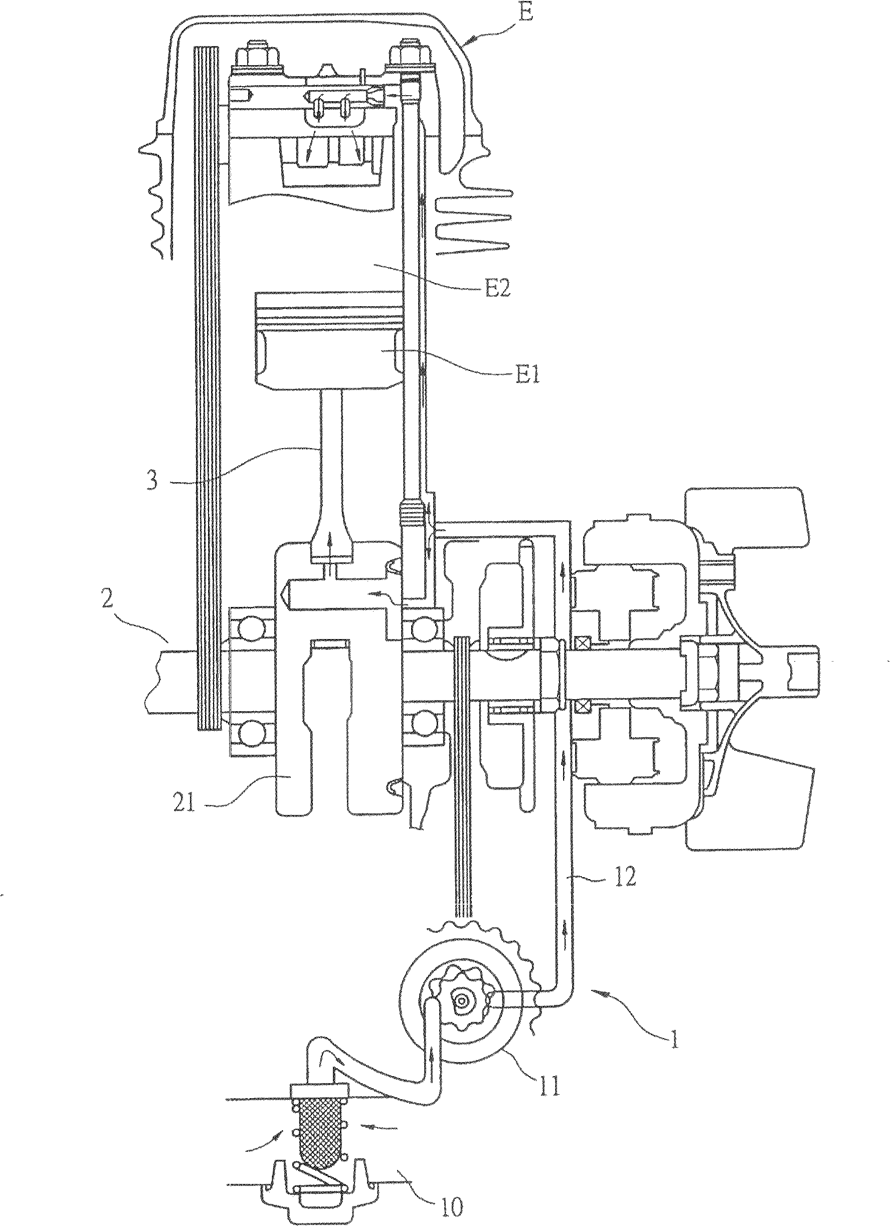
[0026] The present invention is mainly about the filtering device of the crankshaft lubricating oil, other lubricating parts of the engine without modification, so it will not be described in detail. Below, only the part of the present invention will be described in detail, and it will be described first.

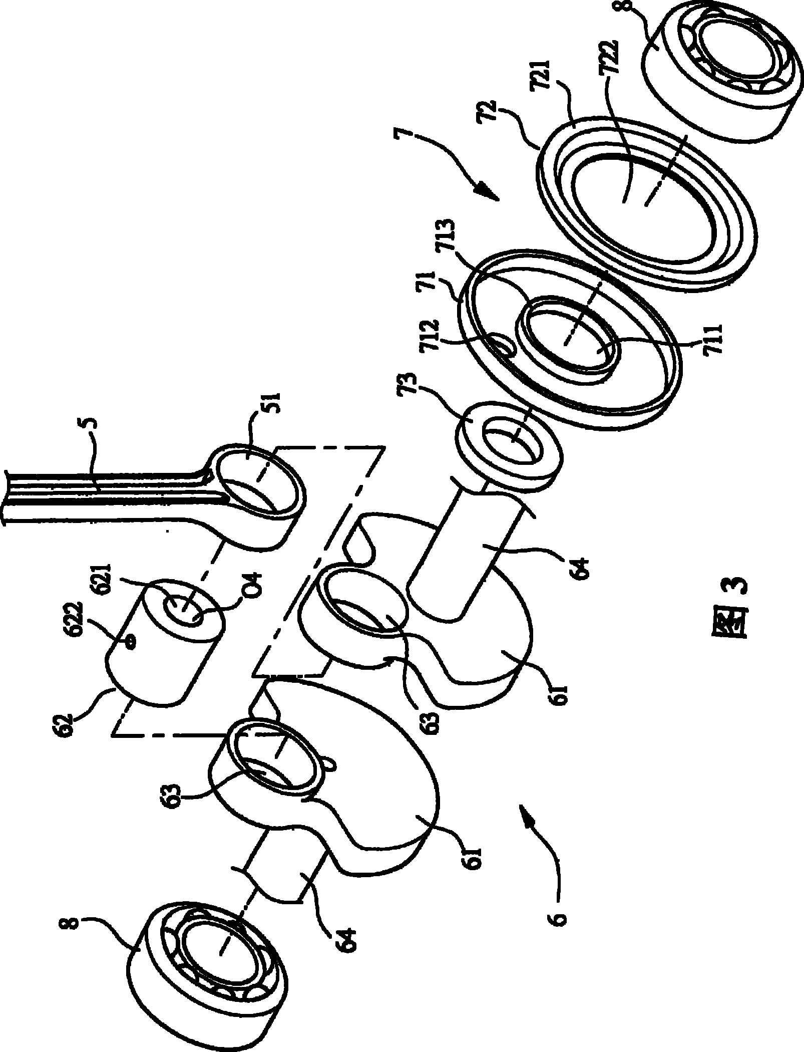
[0027] First, please refer to Figures 3 and 4, the bottom end of the piston connecting rod 5 has a connection hole 51, the connection hole 51 can be used for the penetration of the crank pin 62, and the crank pin 62 is then inserted into the crank connection hole 63, Piston connecting rod 5 promptly gets connected with crankshaft 6 by this, and can drive crankshaft 6 to make circular motion when piston connecting rod 5 burns and does reciprocating motion in engine (not drawing in ...


PUM


Abstract

This invention relates to one curve shaft lubrication filter device, which comprises one body part and one cover part, wherein, the filter device inside is of hollow shape; the cover is set with one hole an one exit hole and pass hole in the middle to make the filter device set on the curve shaft part between curve shaft matching block and roller axis. This invention uses one body part and one cover to form one independent part widely applied in each kind of matching block curve shaft.

Description

【Technical field】 [0001] The invention relates to a crankshaft lubricating oil filtering device, in particular to a lubricating oil filtering device which can increase the volume of the crankshaft lubricating oil filtering device and can improve the universality of the crankshaft lubricating oil filtering device. 【Background technique】 [0002] The lubrication system of scooter motorcycle engine is as follows: figure 1 As shown, the lubricating system is basically composed of a connected oil tank 10, an oil pump 11, and a delivery pipeline 12. The oil in the oil tank 10 (that is, lubricating oil) is continuously conveyed by the oil pump 11. The pipeline 12 flows to the appropriate place of the engine E, such as the crankshaft 2 in the cylinder E2, the piston E1 and the inner wall of the cylinder E2, to lubricate the engine E, and finally the oil in the cylinder E2 will be recovered into the oil tank 10, so that it can be used repeatedly , to achieve the purpose of lubricati...

Claims


Application Information

Patent Timeline
Patent Type & Authority Patents(China)
IPC IPC(8): F01M11/03F01M1/10
Inventor 苏泓瑜余孟霖陈宪辉
Owner KYMCO
Why Eureka
Try Eureka