Engine crankshaft ventilation system

A technology for crankcase ventilation and engines, which is applied in crankcase ventilation, engine components, machines/engines, etc., to achieve the effects of improving safety, low cost, and simple structure

Inactive Publication Date: 2007-03-07
CHERY AUTOMOBILE CO LTD
View PDF0 Cites 22 Cited by
  • Summary
  • Abstract
  • Description
  • Claims
  • Application Information

AI Technical Summary

Problems solved by technology

A crankcase ventilation system designed for the working principle of a supercharged engine with a complex structure has not been found

Method used


Image

  • Engine crankshaft ventilation system

Examples


Embodiment Construction

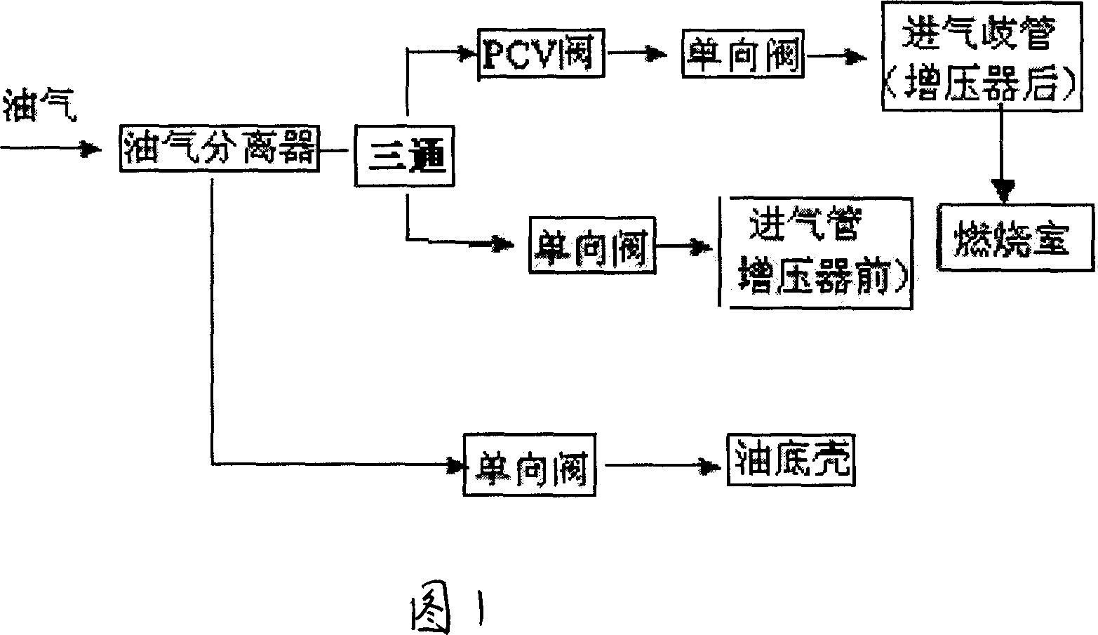
[0010] In the embodiment shown in Fig. 1, a kind of engine crankcase ventilation system comprises PCV valve, oil-gas separator and pipeline; It enters into the oil pan; its characteristic is that the separated gas is divided into two sets of pipelines through the three-way pipe. When the engine is at low speed, the vacuum inside the intake manifold is greater than the vacuum inside the front tube of the supercharger, and the gas enters the intake air. Inside the manifold, at the same time, in order to prevent the air in the front pipe of the supercharger from entering the ventilation pipeline, a check valve needs to be installed between the air pipe in front of the supercharger and the oil-air separator; The vacuum degree is greater than the intake manifold, and the gas enters the air pipe in front of the supercharger. At the same time, in order to prevent the compressed gas in the intake manifold from entering the ventilation system, a check valve needs to be installed between...


PUM


Abstract

This invention discloses one motor curve shaft ventilating system, which comprises PCV valve, oil and gas isolator and pipe path, wherein, it leads out oil gas into oil and gas isolator from curve shaft case gas cover then through PCV valve into gas-in branch tube into oil bottom shell; the isolator and oil bottom tube path are set with single valve; at high speed of motor, gas enters pressure increasing device with one single valve fixed between gas tube and oil and gas isolator.

Description

technical field [0001] The present invention relates to a crankcase ventilation system for an engine, in particular to a crankcase ventilation system which is particularly suitable for a supercharged gasoline engine. Background technique [0002] Due to the existence of piston leakage and the evaporation of oil in the oil pan, the gas pressure inside the crankcase will gradually increase with the increase of the number of engine working cycles, which will cause the oil and gas inside the crankcase to leak out and pollute environment; and as the gas pressure inside the crankcase continues to rise, there will be a danger of violent anger; at the same time, the rise in the internal pressure of the crankcase will increase the resistance of the piston going down, affecting the output of the engine power. Inside the valve chamber cover, due to the very high pressure in the cylinder, the gas will be strung up to the inside of the valve chamber cover at the door guide; in addition, ...

Claims


Application Information

Patent Timeline
Patent Type & Authority Applications(China)
IPC IPC(8): F01M13/04
Inventor 朱小平
Owner CHERY AUTOMOBILE CO LTD
Why Eureka
Try Eureka