Stroke-variable engine

An engine and stroke technology, which is applied in the direction of engine components, combustion engines, machines/engines, etc., can solve the problems of a large number of parts in the valve transmission mechanism, high mechanical noise, and difficulty in achieving high speed, so as to improve durability performance, and the effect of improving installability

Inactive Publication Date: 2007-03-07
HONDA MOTOR CO LTD
View PDF1 Cites 12 Cited by
  • Summary
  • Abstract
  • Description
  • Claims
  • Application Information

AI Technical Summary

Problems solved by technology

[0003] However, in the variable stroke engine disclosed in the aforementioned Japanese Patent Laid-Open No. 2003-314237, the valve transmission mechanism is constituted as an OHV (overhead valve) type in which the rotating shaft also serves as a camshaft. In the case of a mechanism, not only the number

Method used


Image

  • Stroke-variable engine
  • Stroke-variable engine
  • Stroke-variable engine

Examples


Embodiment Construction

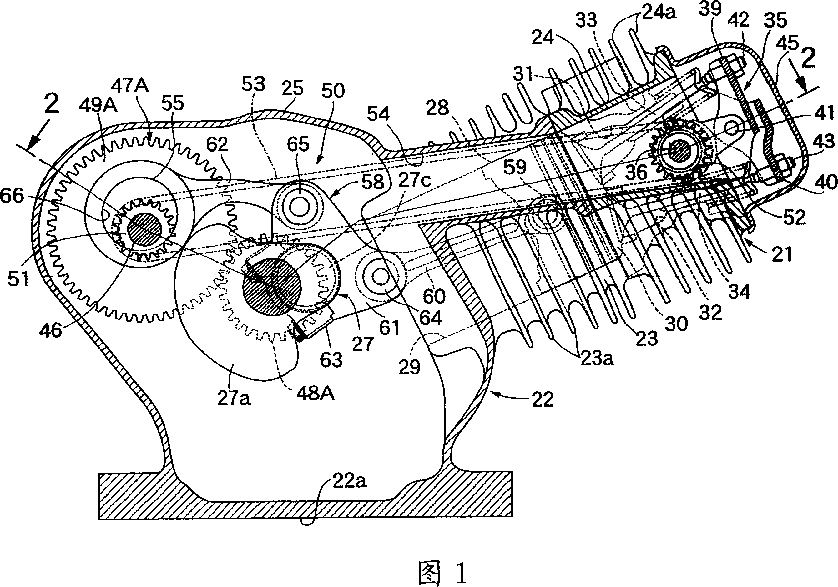
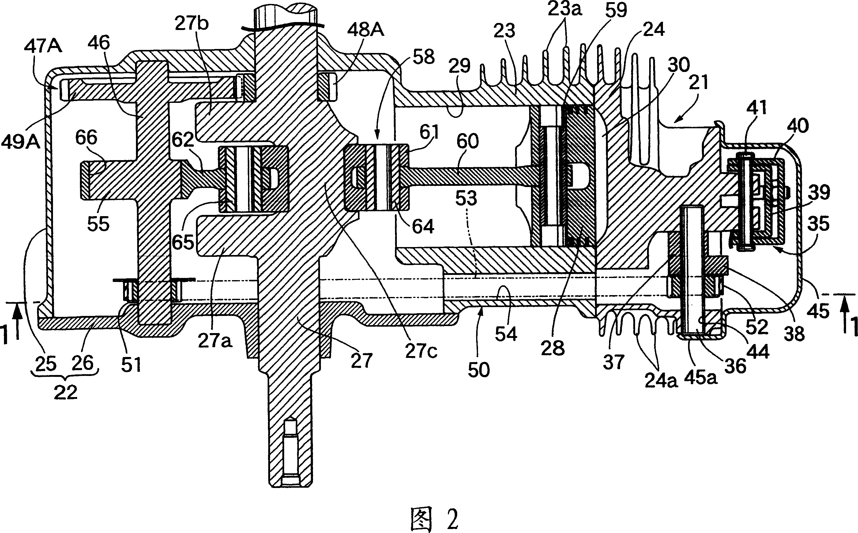
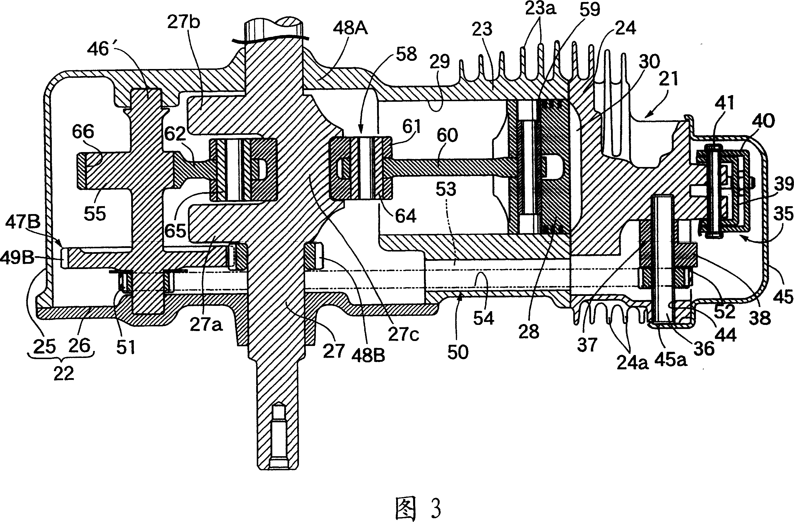
[0021] While referring to Fig. 1 and Fig. 2, the first embodiment of the present invention is described, and this engine is for example utilized in the air-cooled single-cylinder engine in working machine etc., and engine main body 21 is made up of following parts: crankcase 22; 23, which protrudes slightly upward from one side of the crankcase 22; and a cylinder head 24, which is joined to the head of the cylinder block 23, and on the outer sides of the cylinder block 23 and the cylinder head 24, a plurality of air cooling Use fins 23a..., 24a.... In addition, the crankcase 22 is mounted on the engine bed of various working machines by using the mounting surface 22a on the lower surface of the crankcase 22 .

[0022] The crankcase 22 is composed of a case main body 25 which is cast integrally with the cylinder block 23 and which is opened on one side, and a side cover 26 which is joined to the open end of the case main body 25 . The crankshaft 27 integrally includes a pair o...


PUM


Abstract

The present invention provides a variable stroke engine in which there is a pivot shaft which is rotatable around an eccentric axis parallel to the crankshaft and which is freely rotatably supported on the crankcase and at the same time connected to a control rod In this variable stroke engine, the camshaft (36) and The pivot (55) is linked and connected. Therefore, the number of components of the valve train can be reduced, and at the same time, the rotation speed can be increased, and the mechanical noise can be reduced.

Description

technical field [0001] The present invention relates to variable stroke engines, and in particular, to such a variable stroke engine having: a main connecting rod connected at one end to the piston via a piston pin; an auxiliary connecting rod connected to the crankpin of the crankshaft, At the same time, the crankshaft is rotatably supported on the crankcase of the engine main body connected to the other end of the above-mentioned main link; and a pivot shaft, which is connected to the other end of the above-mentioned control rod, is rotatable about an eccentric axis parallel to the above-mentioned crankshaft, and is rotatably supported on the above-mentioned crankcase, and at the same time, transmits a deceleration from the above-mentioned crankshaft by 1 / 2 Power after deceleration. Background technique [0002] In the past, such a variable stroke engine has been known in Japanese Patent Application Laid-Open No. 2003-314237, etc., in which one end of the control rod is c...

Claims


Application Information

Patent Timeline
IPC IPC(8): F02B75/32F01L1/348
CPCF02B41/04F02B75/048
Inventor 渡边生
Owner HONDA MOTOR CO LTD
Why Eureka
Try Eureka