Electromagnetic fuel injection valve

A fuel injection valve, electromagnetic technology, applied in the direction of fuel injection device, charging system, engine components, etc., can solve the problem of low noise suppression effect, achieve the effect of suppressing working noise, overall compactness, and improving strength

Active Publication Date: 2007-03-07
HITACHI ASTEMO LTD
View PDF2 Cites 3 Cited by
  • Summary
  • Abstract
  • Description
  • Claims
  • Application Information

AI Technical Summary

Problems solved by technology

On the other hand, the glass fiber in the resin molded part is a material that easily transmits noise. Although a part of the solenoid case is covered by the two-layer structure of the vibration-proof body and the resin molded part, the suppression effect of the operating noise is very low.

Method used


Image

  • Electromagnetic fuel injection valve
  • Electromagnetic fuel injection valve
  • Electromagnetic fuel injection valve

Examples


Embodiment 1

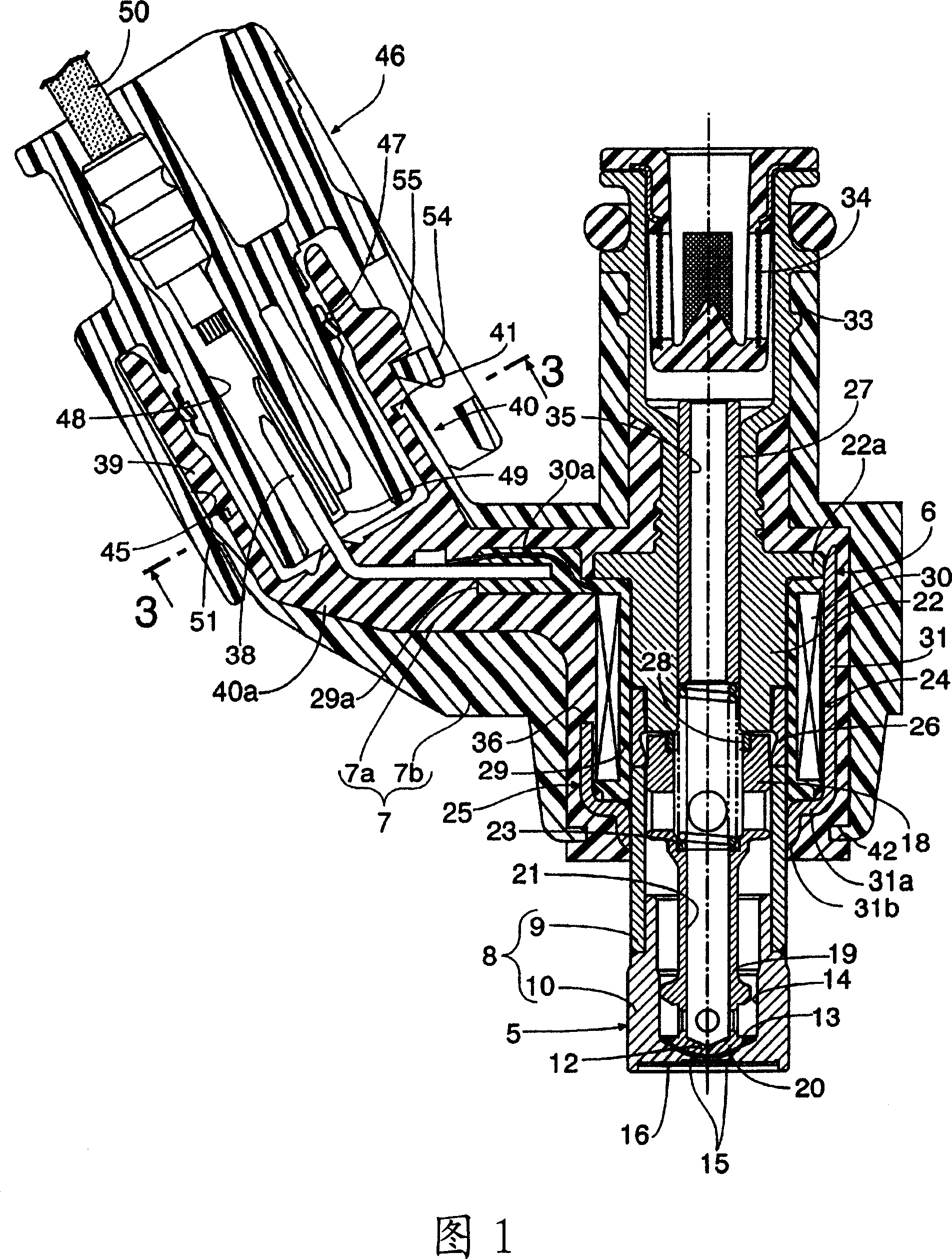
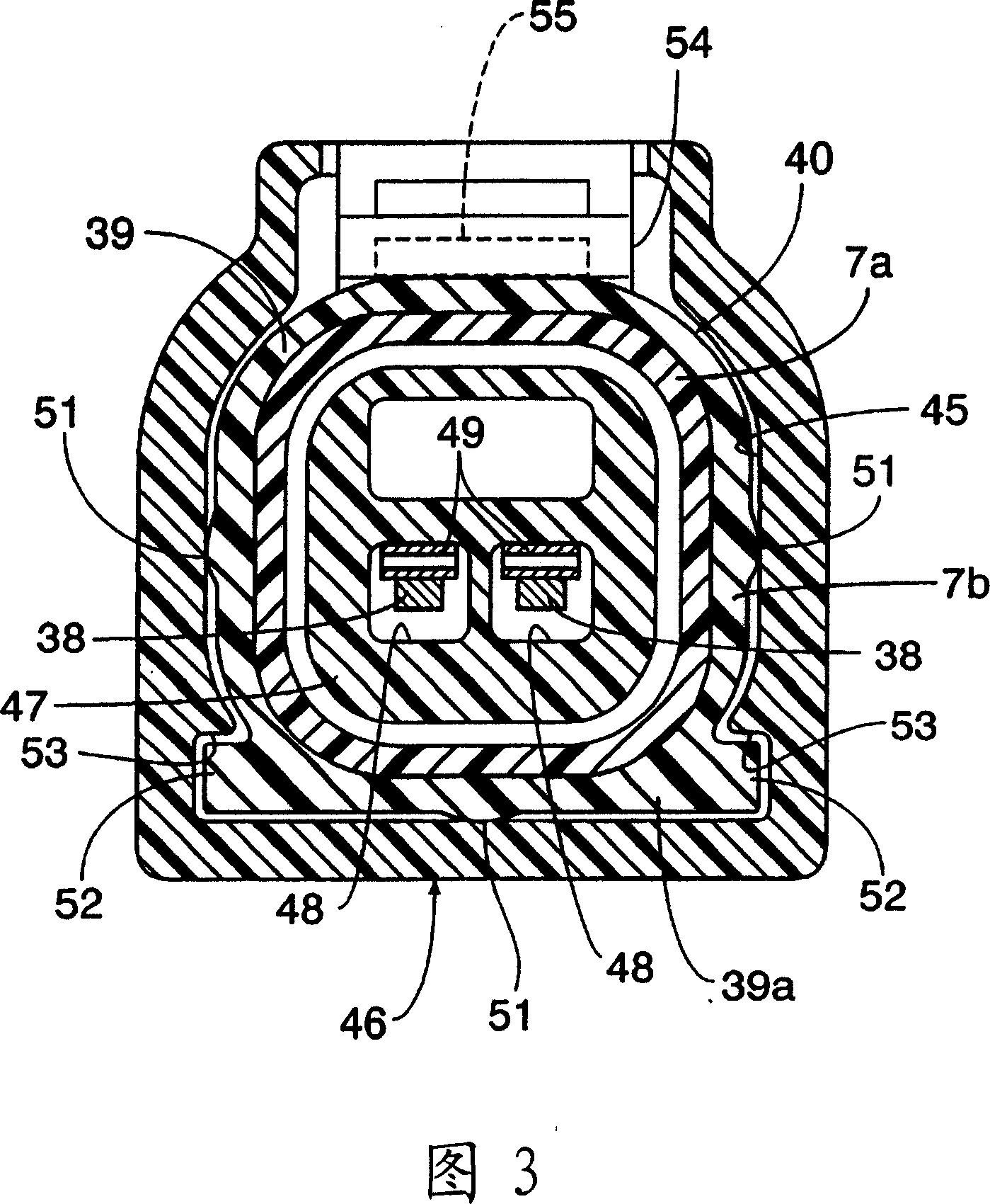
[0040] 1 to 3 show a first embodiment of the present invention.

[0041] First, in FIG. 1 , an electromagnetic fuel injection valve for injecting fuel to an engine not shown has a valve operating part 5 configured to house a valve body 20 in a valve housing 8 . There is a valve seat 13 at the front end, and the valve body 20 is elastically applied to the direction of falling on the valve seat 13; the electromagnet part 6 is configured to accommodate a coil assembly 24 in an electromagnet housing 25, and the The electromagnet housing 25 is connected to the valve housing 8, and the coil assembly 24 can generate an electromagnetic force that drives the valve body 20 in a direction away from the valve seat 13; and the resin made of synthetic resin The forming part 7 integrally has the power receiving connector 40 and embeds at least the coil assembly 24 and the electromagnet case 25, wherein the power receiving connector 40 faces to be assembled with the coil. The power receiving...

Embodiment 2

[0071] As a second embodiment of the present invention, as shown in FIG. 4 , an annular engagement groove 57 connected in the middle of the power receiving connector 40 may also be provided on the first resin molding layer 7a, and its horizontal The cross-sectional shape is substantially V-shaped, and is engaged with the second resin molded layer 7b.

Embodiment 3

[0073] As a third embodiment of the present invention, as shown in FIG. 5 , on the first resin molding layer 7a, a ring-shaped engagement groove 58 may be provided in the middle part of the power receiving connector 40, which is wedge-shaped. Engages with the second resin molded layer 7b.

[0074] In addition, as another example of the present invention, roughening may be performed on the outer surface of the portion covered by the second resin molding layer 7b in the first resin molding layer 7a, or corrugation may be formed on the outer surface. Concave-convex shape, in order to improve the adhesion between the first and second resin molded layers 7a, 7b.


PUM


Abstract

The present invention provides an electromagnetic fuel injection valve having a resin molded part made of synthetic resin, the resin molded part integrally has a connector and embeds at least a part of an electromagnet case, the connector faces A connecting terminal connected to a coil of a coil assembly, wherein the resin molding part (7) is composed of a first resin molding layer (7a) and a second resin molding layer (7b), and the first resin molding layer (7a) covers at least the electromagnetic A part of the iron shell (25), and constitutes at least a part of the connector (40), the first resin molding layer (7a) is formed by a synthetic resin mixed with glass fibers; the second resin molding layer (7b) covers the first The resin forming layer (7a) is formed of thermoplastic polyester rubber not mixed with glass fiber. Thereby, sufficient strength can be ensured to obtain reliability of the electrical connection portion, generation of operation noise can be effectively suppressed, and compactness can be achieved.

Description

technical field [0001] The present invention relates to an electromagnetic fuel injection valve, in particular to such an electromagnetic fuel injection valve: comprising: a valve working part, which is configured to accommodate a valve body in a valve housing, the valve housing has a valve seat at the front end, The valve body is applied with elastic force in the direction of falling on the valve seat; the electromagnet part is configured to accommodate a coil assembly in the electromagnet housing, and the electromagnet housing is connected to the valve housing. , the coil assembly can generate electromagnetic force to drive the valve body away from the valve seat, and a resin molded part made of synthetic resin, the resin molded part integrally has a power receiving connector, and At least a part of the electromagnet case is sealed, and the power receiving connector faces a connection terminal connected to a coil of the coil assembly. Background technique [0002] Among s...

Claims


Application Information

Patent Timeline
Patent Type & Authority Applications(China)
IPC IPC(8): F02M51/06F02M51/08F02M61/16
Inventor 松尾大辅佐藤和彦大村知之佐藤健一日向修
Owner HITACHI ASTEMO LTD
Why Eureka
Try Eureka