Electric motor load judgment method

A technology of load judgment and motor, applied in the field of motor, to achieve the effect of reducing circuit complexity, simple and easy method, and increasing hardware cost

Active Publication Date: 2007-03-14
HAIER GRP CORP +1
View PDF2 Cites 11 Cited by
  • Summary
  • Abstract
  • Description
  • Claims
  • Application Information

AI Technical Summary

Problems solved by technology

Above-mentioned prior art obvious

Method used


Image

  • Electric motor load judgment method

Examples


Embodiment Construction

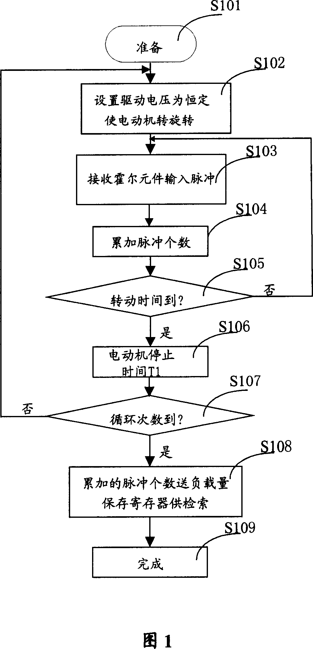
[0026] Please refer to FIG. 1 , which is a flow chart of the first embodiment of the present invention. The motor in this embodiment is a DC brushless motor with a Hall element. In order to clearly illustrate the present invention, a brief description of the principle of the DC brushless motor with Hall elements is given below. Brushless DC motor is a kind of motor widely used in household appliances at present, and most of them use Hall elements as position sensors to control the voltage on and off of each phase of the stator.

[0027] The DC brushless motor uses a permanent magnet rotor, and the required number of Hall devices are placed in the appropriate position of the stator, and their outputs are connected to the corresponding power supply circuit of the stator winding. When the rotor passes near the Hall device, the magnetic field of the permanent magnet rotor makes the energized Hall device output a voltage, turns on the stator winding power supply circuit, supplies ...


PUM


Abstract

The disclosed load decision method for dc brushless motor and ac motor with speed feedback loop comprises: 1) setting constant drive voltage to rotate the motor; 2) receiving the input pulse from Hall element of the dc brushless motor or pulse signal from speed feedback of ac motor; 3) accumulating pulse number in one period; 4) deciding load according to pulse number. Wherein, it is better to turn back to step 1) after 3), and repeats steps 1)-3) for some times. This invention is convenient and well precise.

Description

technical field [0001] The invention relates to electric motors, in particular to a method for judging the load of the electric motor. Background technique [0002] When using a motor as power, it is often necessary to know the size of the load. For example, in the application of home appliances, the washing machine needs to fuzzily determine the water consumption, heating time, drying time, etc. according to the load size (that is, the amount of clothes). [0003] In the case of ordinary motors as power, the method of detecting the number of counter electromotive force pulses is usually used to obtain the fuzzy parameters of the amount of clothes; in addition, the magnitude of the current can also be used as the basis for judging the magnitude of the load. The above methods all need to set up a dedicated circuit to deal with. This undoubtedly increases the complexity and cost of the circuit. [0004] According to the relationship that the speed of the motor decreases wit...

Claims


Application Information

Patent Timeline
IPC IPC(8): G01R31/34D06F33/02
Inventor 姜德志黄静莉李莉王袭奚丽亚吴宇昊
Owner HAIER GRP CORP
Why Eureka
Try Eureka