
Control method for curved-tooth angle gear chamfering

A technology of a spiral bevel gear and a control method, applied in the field of gear processing, can solve problems such as difficult quality assurance, and achieve the effects of long service life, smooth operation and meshing, and easy understanding.

Inactive Publication Date: 2007-03-14
TIANJIN NO 1 MACHINE TOOL WORKS
View PDF0 Cites 7 Cited by
  • Summary
  • Abstract
  • Description
  • Claims
  • Application Information

AI Technical Summary

Problems solved by technology

However, manual chamfering is not only difficult to guarantee in quality, but also has problems in labor protection.

Method used


Image

  • Control method for curved-tooth angle gear chamfering
  • Control method for curved-tooth angle gear chamfering

Examples


Embodiment 1

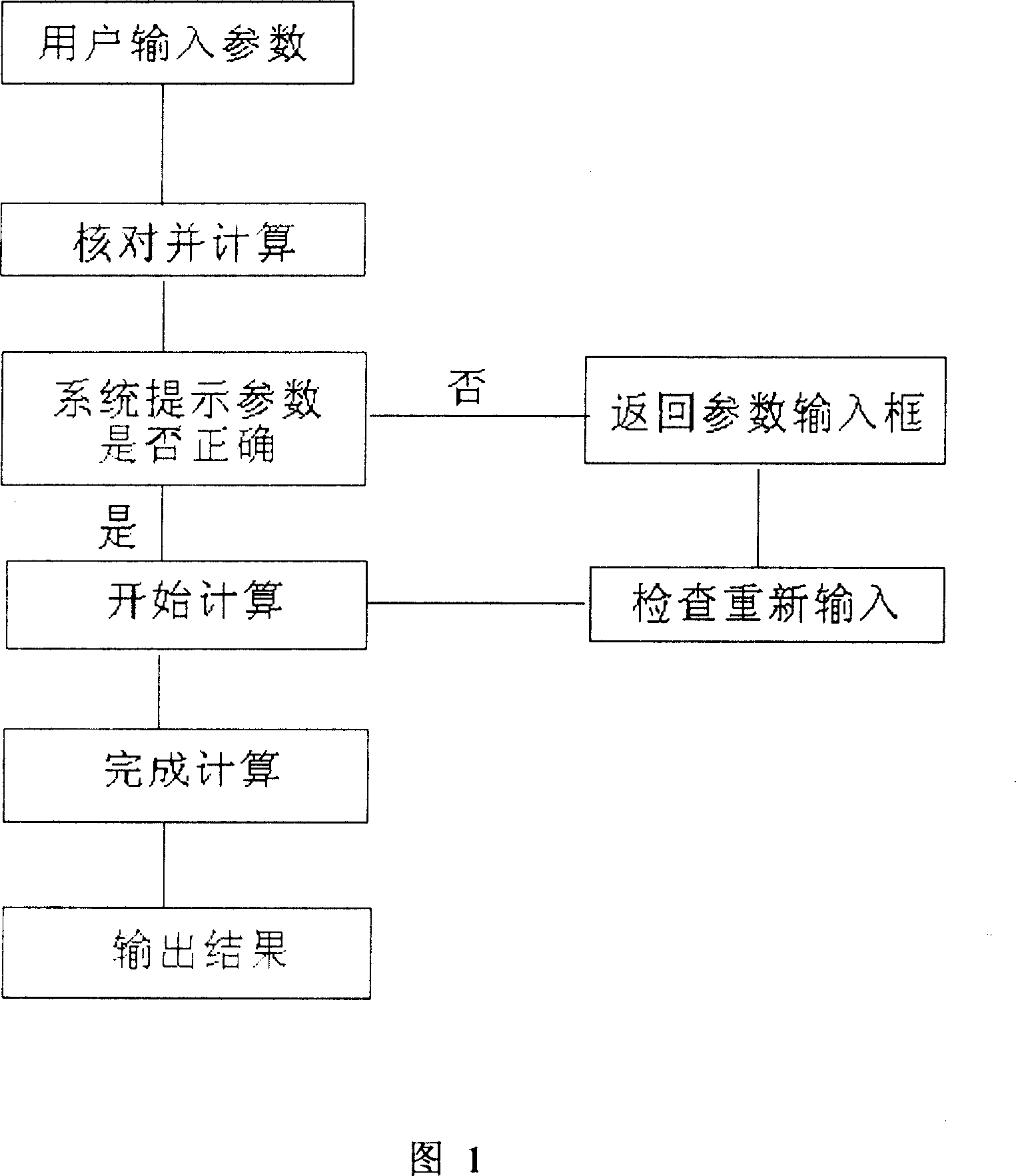
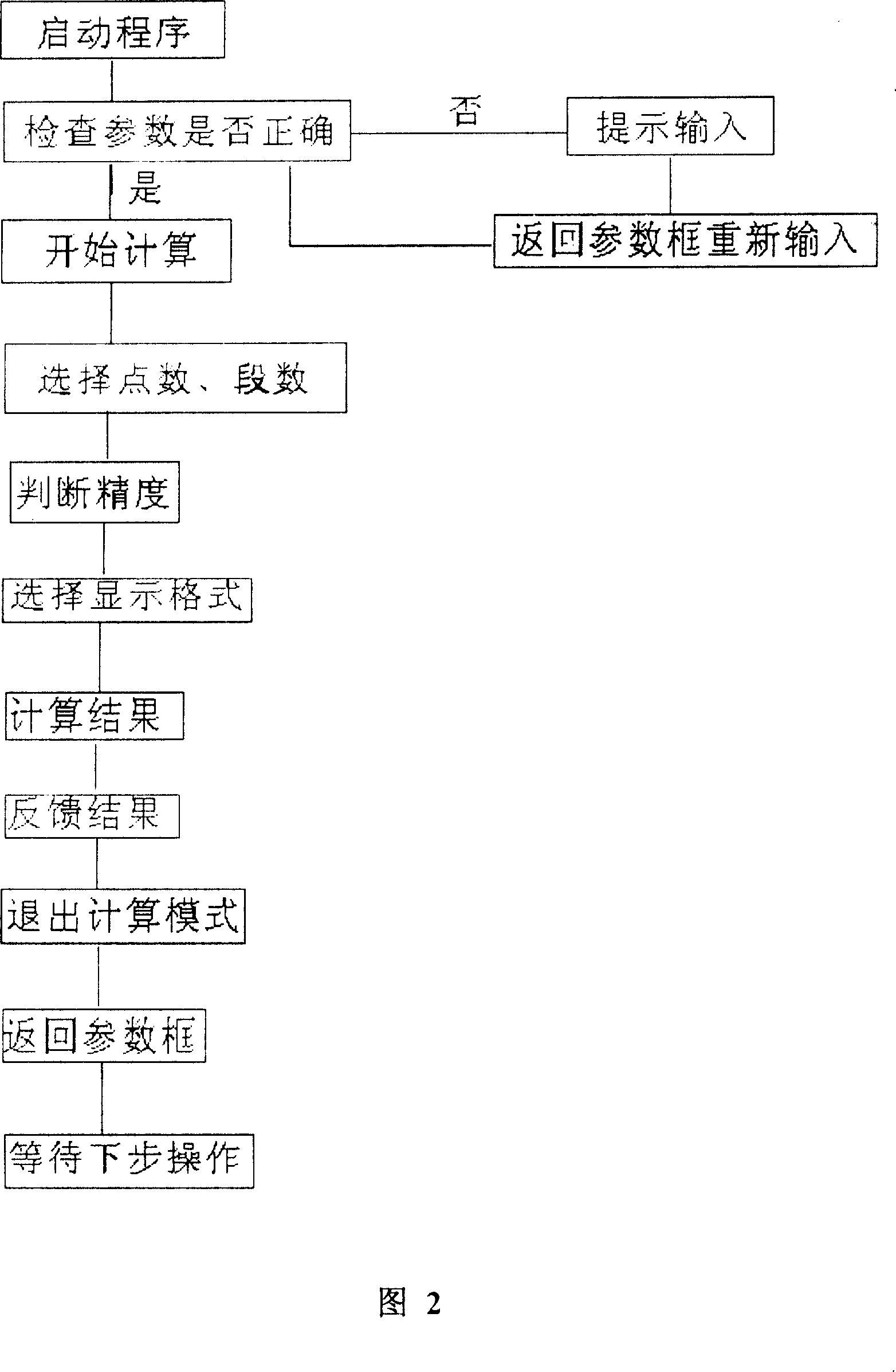
[0026] With reference to accompanying drawing 1 and Fig. 2.

[0027] The method of controlling the chamfering of the spiral bevel gear controls the three-axis linkage machine tool. According to the layout of the chamfering machine tool and the coordinates of the movement, the spiral bevel gear machining calculates and controls the conical positioning tool and the tooth top ridgelines on both sides of the concave and convex tooth grooves, and determines the position between the chamfered workpiece tooth groove and the workpiece spindle of the machine tool The relationship between the tool and the tooth top ridge line on both sides of the concave and convex of the tooth groove is double-touched; the control of the three-axis linkage machine tool for gear chamfering processing is realized.

[0028] Calculation control includes the stage of automatic analysis, the stage of segmented calculation according to the input parameters, the stage of numerical feedback prompt, and the stag...


PUM


Abstract

The related chamfering control method for spiral bevel gear comprises: according to machine tool configuration and movable coordinate, calculating and controlling cone positioning knife and tooth-space convex-concave side crest line to determine the position relation between work piece tooth space and main shaft of machine tool for double touch. Wherein, the control calculation is based on bi-face chamfering. This invention is simple and convenient.

Description

technical field [0001] The invention belongs to the technical field of gear processing, in particular to a method for controlling the chamfering of a spiral bevel gear. Background technique [0002] Spiral bevel (or hypoid) gear pairs are used in almost all automobiles. In addition to their maintenance spare parts, the current annual output is tens of millions of pieces, and it will expand in the future. Defects are often left near the top edge of the tooth surface due to residual thorns left by cutting or grinding teeth, bumps in handling or assembly, and roughening. Therefore, in the meshing operation of the gear pair, it will cause noise, affect the service life and other disadvantages. For this reason, the chamfering process is generally adopted to remove the above-mentioned defects, and then eliminate the above-mentioned adverse consequences. In foreign countries, although individual manufacturers have already produced products that complete the chamfering process mac...

Claims


Application Information

Patent Timeline
Patent Type & Authority Applications(China)
IPC IPC(8): G05B19/02G05B19/18B23F19/10
Inventor 张英章王彦旭王秀梅
Owner TIANJIN NO 1 MACHINE TOOL WORKS
Learn More