

Cutting method for digital controlled flame cutter
A technology of flame cutting machine and cutting method, which is applied in the direction of digital control, gas flame welding equipment, comprehensive factory control, etc., can solve the problems of wasted warm-up time, low labor efficiency, and slow work efficiency, etc., to prolong the service life and improve Labor efficiency and effect of small amount of deformation
- Summary
- Abstract
- Description
- Claims
- Application Information
AI Technical Summary
Problems solved by technology
Method used
Image

Examples
Embodiment 1
[0035] The cutting method of numerical control flame cutting machine, it comprises the following steps:
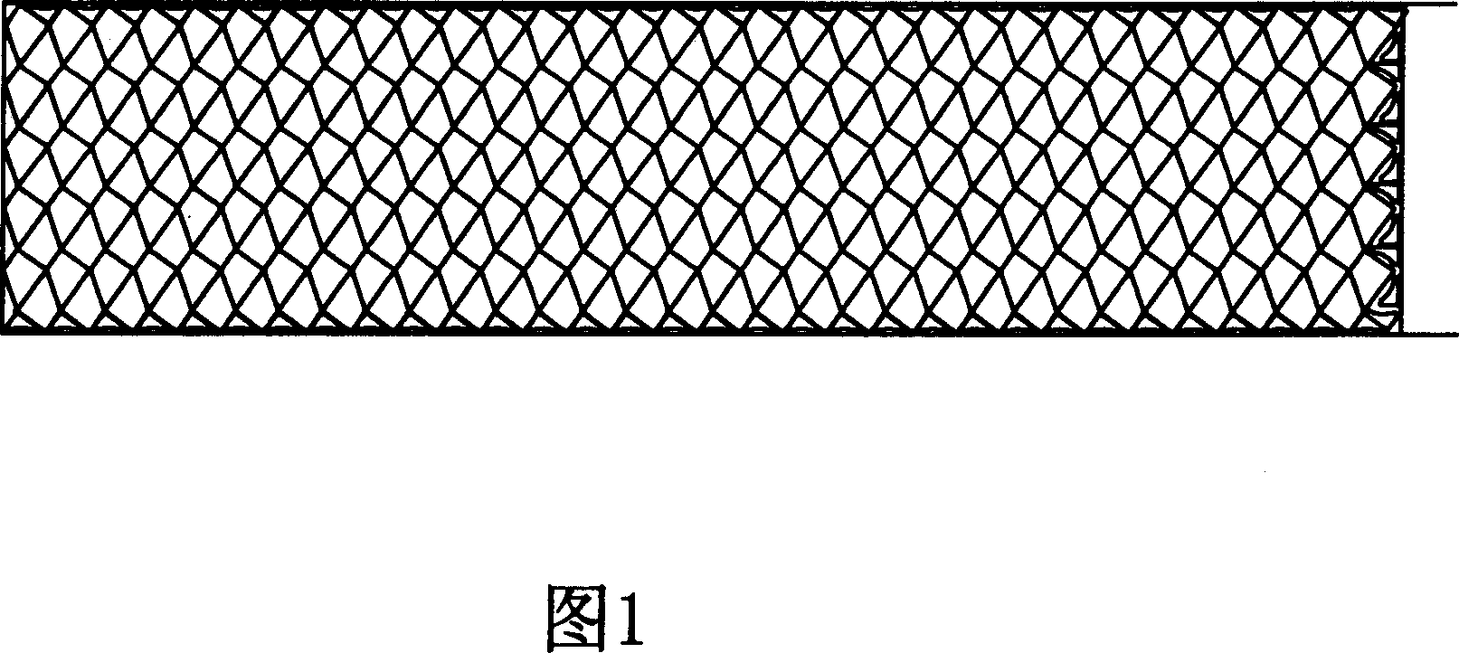
[0036] a. Drawing file design step: This step is used to draw according to the shape of the finished part and the specifications of the sheet to be cut to draw a drawing file, which includes a plurality of closed circular graphics elements equivalent to the shape of the finished part;
[0037] b. Cutting path design step: this step is used to design the cutting path according to the drawings, and define the cutting processing code according to the cutting path;
[0038] c. Processing code input step: This step is used to transmit the cutting processing code of the previous step to the processing center of the cutting machine through the man-machine exchange module of the cutting machine;
[0039] d. Cutting step: This step is used by the machining center to cut the plate according to the cutting processing code in the previous step to generate finished parts; the cutting s...
Embodiment 2
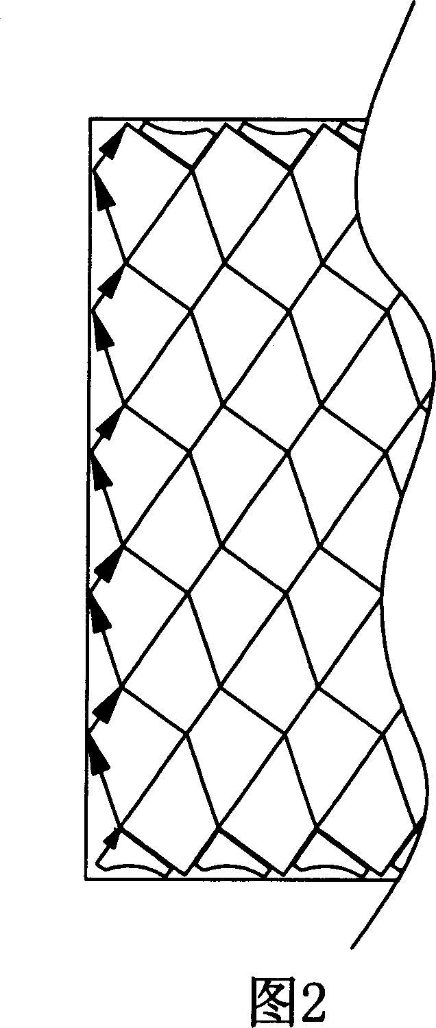
[0044]The difference between this embodiment and the first embodiment lies in that the shape of the finished part of the present invention is an equilateral hexagon, that is, the graphic element is an equilateral hexagon. The graphic file in the described graphic file design step, in combination with the general thinking of the present invention, each graphic element is arranged in the following manner: the graphic element is symmetrically arranged, the first diagonal line is parallel to the first direction, and each graphic element is the same The edges are the same so that all the primitives are closely arranged to reduce scraps. Wherein, the first diagonal divides the equilateral hexagon into two symmetrical halves, the left and the right, and the said picture file is a picture file drawn without repetition.
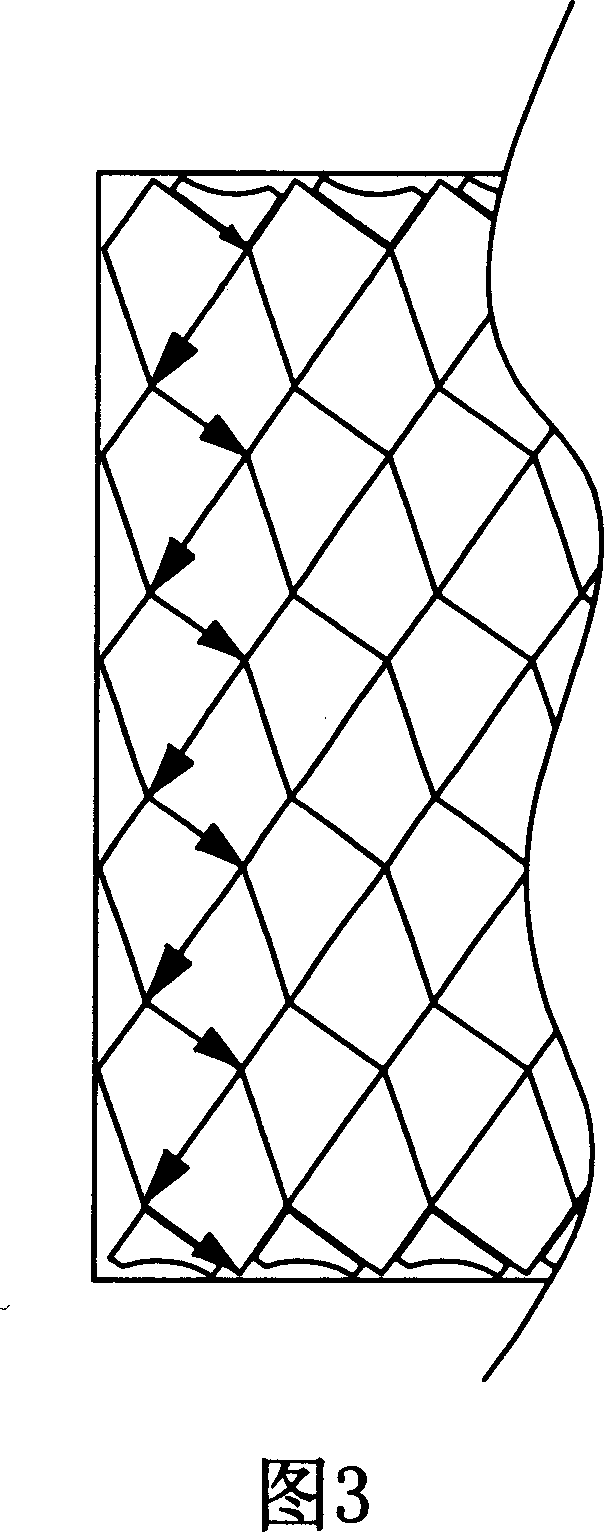
[0045] Cutting path in the cutting path design step: the cutting path includes a plurality of first paths along the first direction and composed of parts of the same ...
Embodiment 3
[0047] The difference between this embodiment and Embodiment 1 is that, as shown in FIG. 5 , the shape of the finished part of the present invention is a triangular shape, that is, the graphic element is a triangular shape. The picture files in the picture file design step, in combination with the general thinking of the present invention, each graphic element is typesetting in the following way: divided into several sub-picture files that are arranged without repetition. Among them, each sub-graph file: every two graphics elements cooperate to form a quadrilateral with a diagonal line, and several quadrilaterals are arranged side by side.
[0048] Cutting path in the cutting path design step: the cutting path includes several rows of the first path along the second direction and composed of the same row of graphic elements. All parts of the row are cut in one pass along the first pass. The cutting process of the cutting path of the present invention is shown in Figures 6 and...
PUM
 Abstract
Description
Claims
Application Information