Motor rotor pin jointing structure
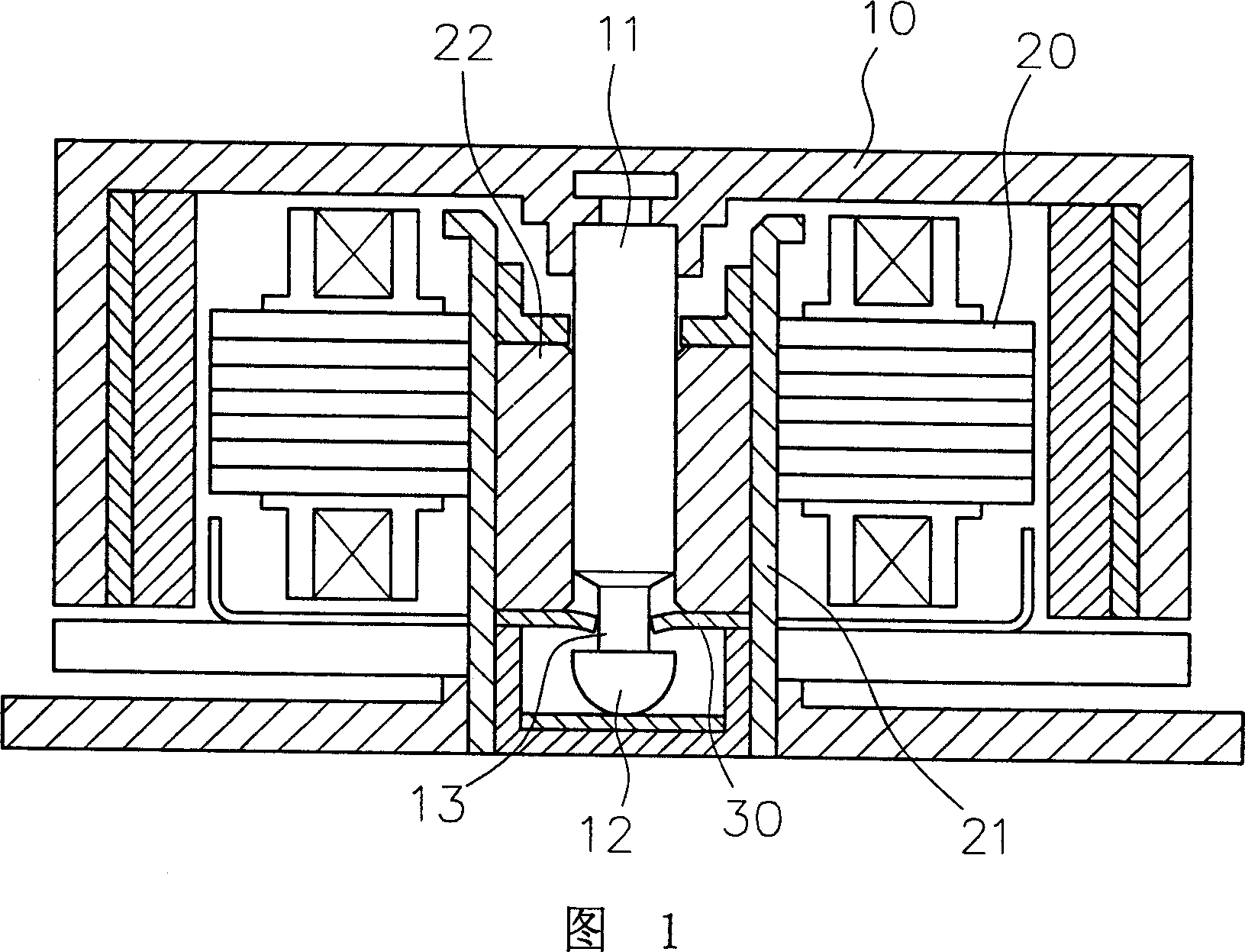
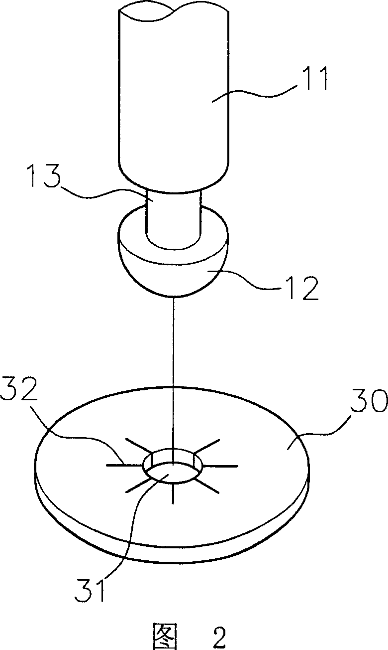
A motor rotor and pivot joint technology, which is applied in the field of motor rotor pivot joint structure, can solve the problems that the clasp 30 is broken and damaged, cannot be disassembled, and the clasp 30 and the mandrel 11 are prone to friction noise, etc. Noise, stability improvement effects
- Summary
- Abstract
- Description
- Claims
- Application Information
AI Technical Summary
Problems solved by technology
Method used
Image
Examples
Embodiment Construction
[0020] The preferred embodiments of the present invention are listed below and the relative positional relationship of the various components of the present invention will be described in detail with reference to the accompanying drawings.
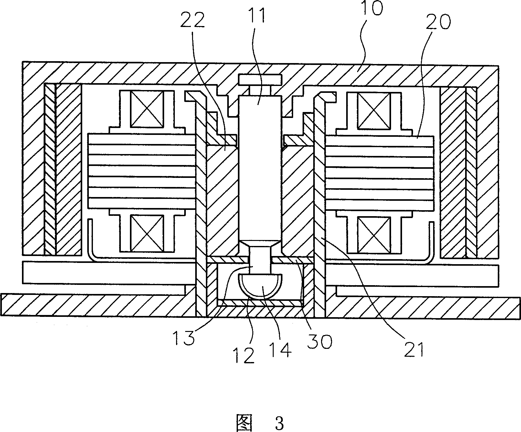
[0021] As shown in Figure 3, the motor is mainly composed of a rotor 10 and a stator 20, wherein:
[0022] A mandrel 11 is arranged in the center of the rotor 10 , and the end side of the mandrel 11 near the abutting portion 12 has a groove 13 with a smaller outer diameter.
[0023] The stator 20 is sleeved on the outer periphery of a shaft tube 21 , and a bearing 22 is installed in the shaft tube 21 , and the spindle 11 of the rotor 10 is driven to rotate in the center of the bearing 22 .
[0024] As shown in FIG. 4 , it is the first embodiment of the present invention. The abutting portion 12 of the mandrel 11 is provided with two parallel axial sections 14, so that the section of the abutting portion 12 forms a non-circular shape, and t...
PUM
 Abstract
Description
Claims
Application Information
 - R&D
- Intellectual Property
- Life Sciences
- Materials
- Tech Scout
- Unparalleled Data Quality
- Higher Quality Content
- 60% Fewer Hallucinations
Browse by: Latest US Patents, China's latest patents, Technical Efficacy Thesaurus, Application Domain, Technology Topic, Popular Technical Reports.
© 2025 PatSnap. All rights reserved.Legal|Privacy policy|Modern Slavery Act Transparency Statement|Sitemap|About US| Contact US: help@patsnap.com


