Turbine and rotor therefor

A rotor and turbine technology, applied in the field of rotors/propellers, can solve problems such as low reliability and increased turbine noise

Inactive Publication Date: 2007-03-14
弗兰克·丹尼尔·洛特里翁特
View PDF0 Cites 21 Cited by
  • Summary
  • Abstract
  • Description
  • Claims
  • Application Information

AI Technical Summary

Problems solved by technology

[0002] Most modern wind turbine rotors have low reliability and have a small number of airfoil sections with long straight blades around a central horizontal axis with a large proportion of the wind turbine rotor blade area in the inner half of its diameter
The very high tip speeds involved for maximum efficiency can greatly increase the noise of these turbine operating conditions

Method used


Image

  • Turbine and rotor therefor
  • Turbine and rotor therefor
  • Turbine and rotor therefor

Examples


Embodiment Construction

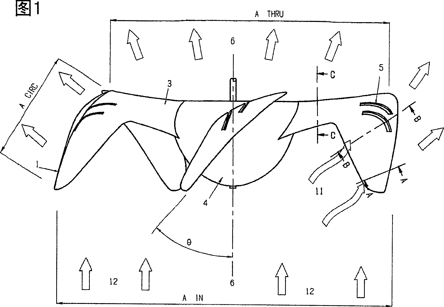
[0040] Refer to Figure 1

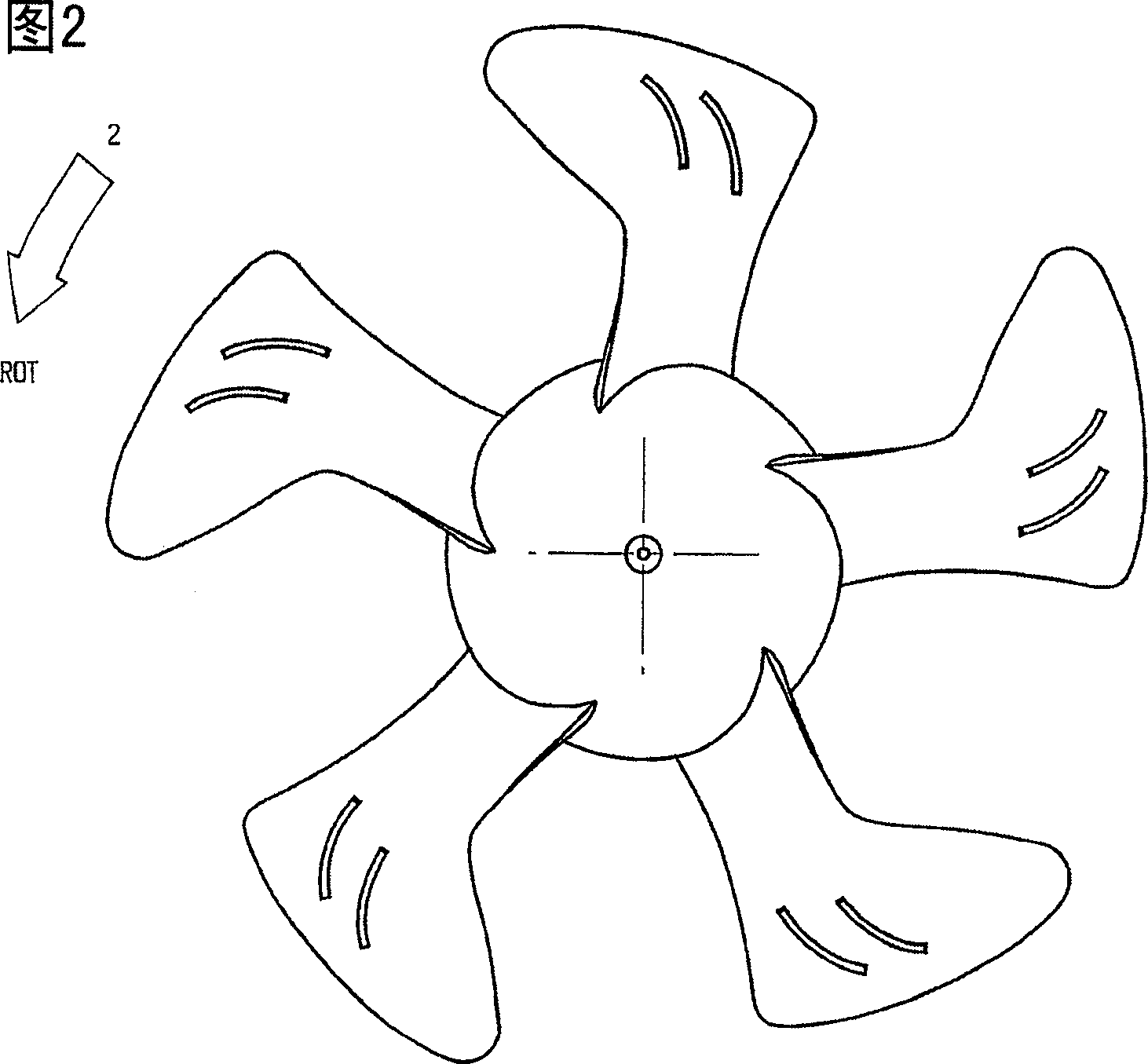
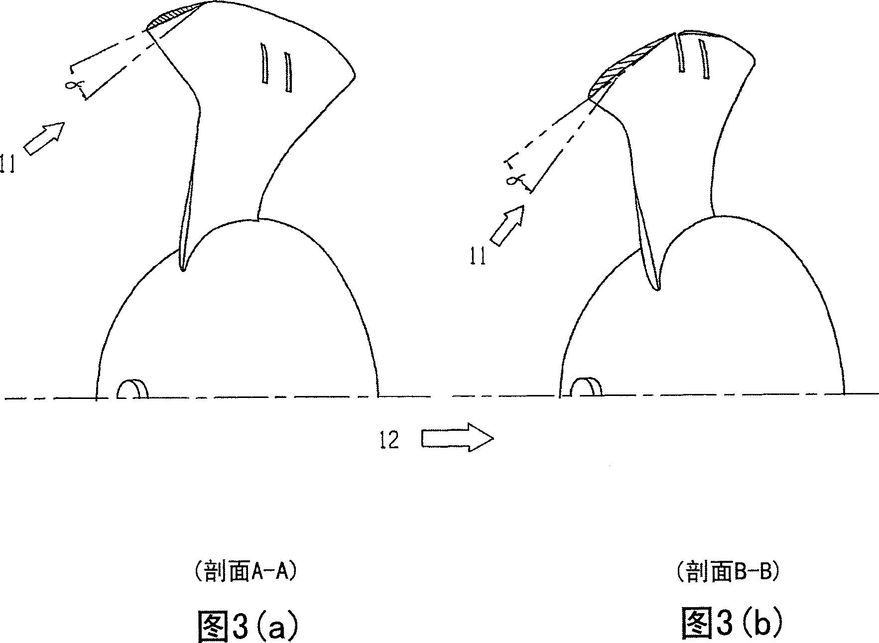
[0041] Several equidistantly spaced integrally formed "hook" blade / wing units comprising the most preferred inner airfoil section blade #3 angled slightly rearward from central hub or shaft #4 substantially Extending radially outward, each inner vane has a leading edge and is also inclined rearwardly from normal between 5 and 60 degrees, and the substantially forward projecting wing section #1 is aligned with the central hub or shaft #4 is integrally formed and attached to its outer outward edge, and the entire blade / wing unit is generally twisted at a helical or oblique angle θ around hub / shaft centerline #6, which is preferably parallel to Air / liquid flow direction #12 to maximize the lift or deflection force derived from the resulting liquid flow and converted to applicable torque.

[0042] Airfoil section #1 is the preferred airfoil section that reduces the chord length in proportion to the distance from inner blade section #3 to form a curved o...


PUM


Abstract

A rotor that consists of a central hub or shaft and a plurality of boot shaped integral blade/vane units that combine a pronounced elongated vane tip extending substantially toward the incoming flow and also the direction of rotation forming a helix or pitch angle to the rotation axis centreline, preferably normal to and joined to the outer frontward extremity of a slightly rearward tilted blade/wing section that is connected by its inner end to the central hub of shaft. The rotor revolves about the rotation axis by incoming gas/fluid flow as most of the fluid flow is encouraged to move substantially outward and rearward as it travels into and past the forwardly projecting vane tips located a substantial distance radially from the axis of rotation. This maximises the torque developed and transferred to the hub/shaft in a manner that does not greatly inhibit total through flow, because the combined gas/fluid flow exit area (or gaps between blades/vanes) is much greater than the maximum rotor diameter and subsequently the rotor inlet area, which has the effect of increasing the through flow velocity and thus overall performance. The blades may have slots within them.

Description

technical field [0001] The present invention relates to a turbine and a rotor therefor having an axis of rotation substantially parallel to the gas / liquid flow. More particularly, the present invention relates to a non-hermetic wind / water turbine, or moving rotor / propeller housed in a duct and extracting energy from or converting energy to a moving gas or liquid flow. Background technique [0002] Most modern wind turbine rotors have low reliability and have a small number of airfoil sections with long straight blades around a central horizontal axis, with a large proportion of the wind turbine rotor blade area being in the inner half of its diameter. The very high tip speeds involved for maximum efficiency can greatly increase the noise of these turbine operating conditions. [0003] The present inventors have recognized that the outer third of any turbine rotor does most of the useful work in converting kinetic energy from a moving gas / liquid flow into usable torque, with...

Claims


Application Information

Patent Timeline
Patent Type & Authority Applications(China)
IPC IPC(8): F03D1/06F03D11/00F03B3/12F03B3/04
CPCY02E10/721Y02E10/722Y02E10/223Y02E10/728Y02E10/20Y02E10/72
Inventor 弗兰克·丹尼尔·洛特里翁特
Owner 弗兰克·丹尼尔·洛特里翁特
Why Eureka
Try Eureka