Small non-pin transformer structure

A leadless, transformer technology, applied in the direction of transformer/inductor core, transformer/inductor parts, transformer/inductor coil/winding/connection, etc., can solve the problem of inability to achieve mechanical processing, uneven magnetic field distribution, Overall performance impact and other issues, to achieve the effect of saving effective space, simplifying wiring requirements, and high production efficiency

Inactive Publication Date: 2007-03-21
MORNSUN GUANGZHOU SCI & TECH
View PDF0 Cites 6 Cited by
  • Summary
  • Abstract
  • Description
  • Claims
  • Application Information

AI Technical Summary

Problems solved by technology

This type of transformer has a simple structure, but it cannot be machined and can only be made by hand. The performance of the product varies from person to person, resulting in uneven distribution of the magnetic field and poor insulation.
Due to its low production efficiency, unreliable production and unstable performance, it has a great impact on the overall performance of the product

Method used


Image

  • Small non-pin transformer structure
  • Small non-pin transformer structure

Examples


Embodiment Construction

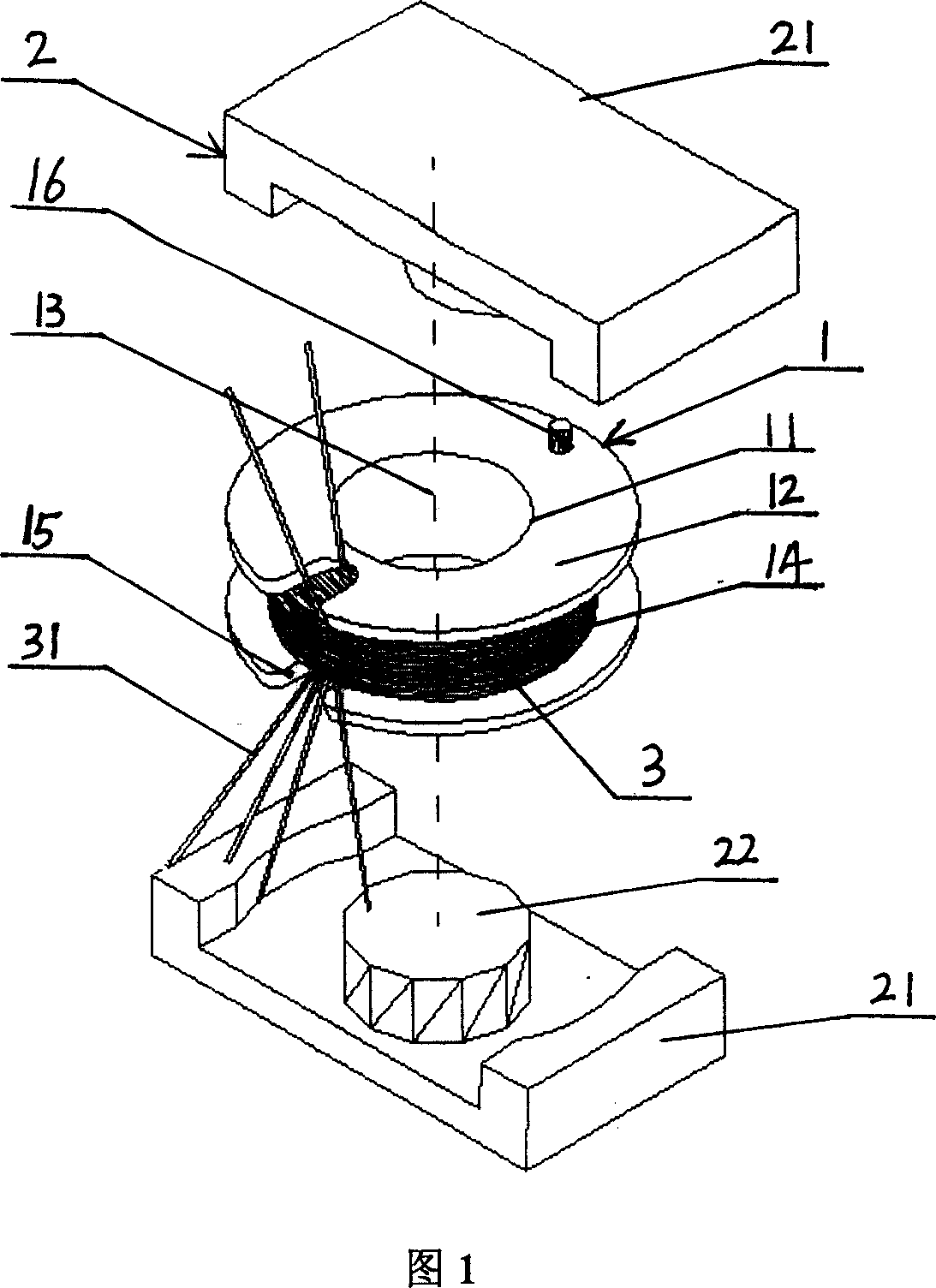
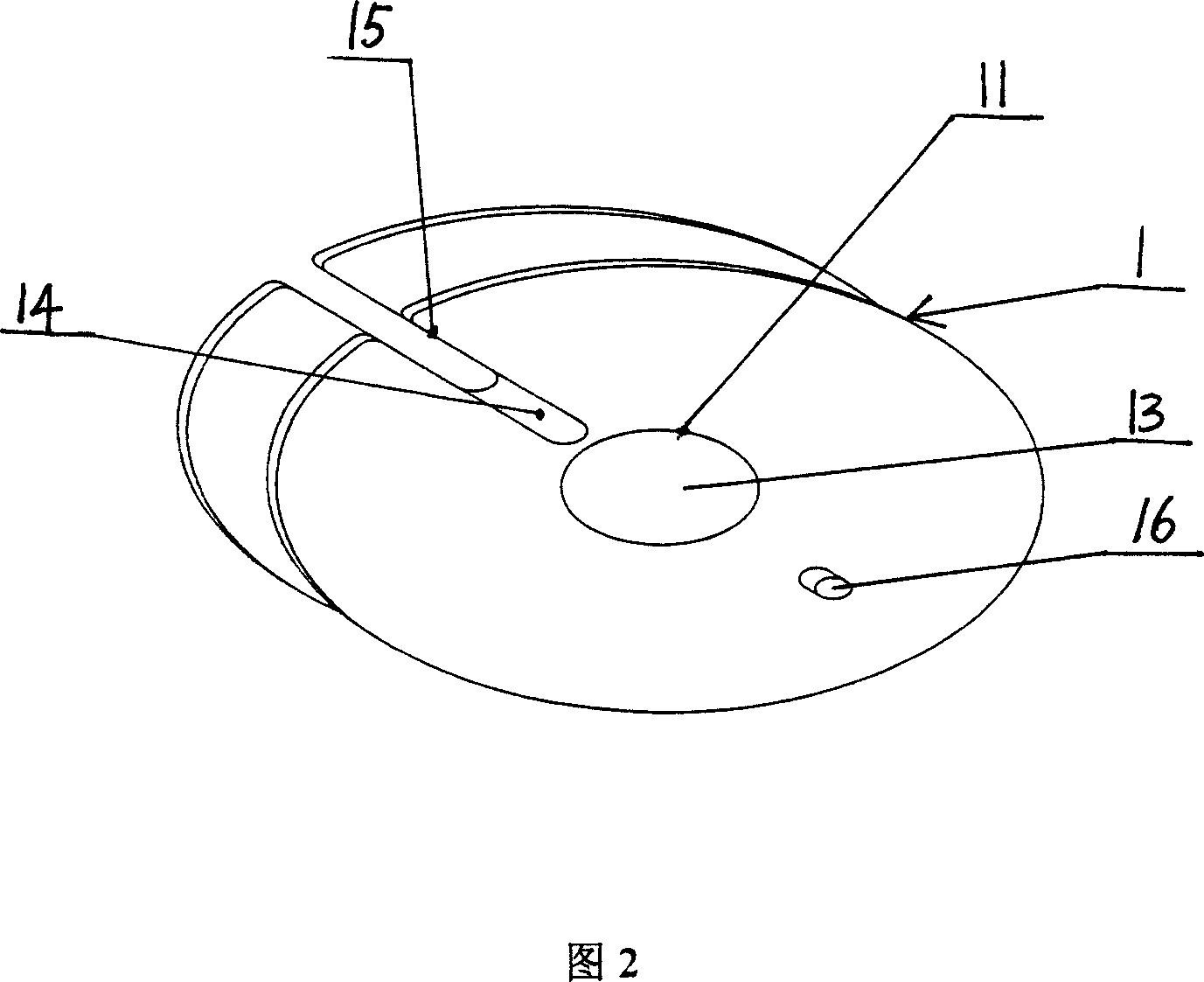
[0017] As shown in Figure 1 and Figure 2, a small PIN-free transformer structure includes a magnetic core, a skeleton, and a winding wire. The skeleton 1 is composed of a bobbin 11 and two ring-shaped end faces 12, and the bobbin 11 has a through shaft hole 13. , two ring-shaped end faces are arranged at both ends of the bobbin and are integrated with the bobbin, and a bobbin groove 14 is formed between the two ring-shaped end faces; the magnetic core 2 is composed of two symmetrical magnetic frames 21, and the magnetic frame is E-shaped. The two magnetic frames face each other, the magnetic core post 22 in the two magnetic frames is placed in the shaft hole 11 of the bobbin, and the skeleton 1 is sandwiched between the two magnetic frames 2, so that the skeleton can rotate around the magnetic core post. The wire 3 is wound in the bobbin groove 14, and the same side of both ends of the skeleton is respectively provided with guide gaps 15 for lead-out wires, and the ends 31 of e...


PUM


Abstract

A small non-pin transformer structure, includes the magnetic core, the skeleton, the winding wire material, the skeleton consists of the bobbin and two ring-type end-face, the axis hole sets in the bobbin, the two ring-type end-face set on both side of the bobbin and form the bobbin slot; the magnetic core sets in the axis hole, and the wire material rolls in the bobbin slot, each end head of the rolling group wire material educes directly to be the connecting pin. The invention can not only be serried lay with other former piece when using to the module power weld, but also use the longer pin to process jump, save the efficient space, predigests the request of making line.

Description

technical field [0001] The invention relates to a transformer structure, in particular to a small pinless (PIN) transformer structure. Background technique [0002] A traditional transformer consists of three parts, a skeleton with a PIN, a winding coil wound on the skeleton, and a magnetic core assembled on the skeleton. At present, the common manufacturing method of transformers is to wind them with a skeleton with PIN, which can be divided into vertical transformers or horizontal transformers. Because the horizontal transformer takes up a lot of space, it is mainly used for high-power products, while the vertical transformer takes up a small space and can be patched or inserted by machine. It is mainly used for low-power power supply products. The vertical transformer is composed of magnetic core, skeleton with PIN, winding wire and its insulating and fixing adhesive tape. Since this kind of transformer has PIN feet, it will occupy a large space on the substrate, which i...

Claims


Application Information

Patent Timeline
Patent Type & Authority Applications(China)
IPC IPC(8): H01F27/30H01F27/24H01F27/00
Inventor 尹向阳
Owner MORNSUN GUANGZHOU SCI & TECH
Why Eureka
Try Eureka