Switching regulator

A stabilizer and switch technology, which is applied in the direction of instruments, adjustment of electric variables, output power conversion devices, etc., can solve the problem that the switch stabilizer cannot work at high speed

Active Publication Date: 2007-03-21
ROHM CO LTD
View PDF2 Cites 6 Cited by
  • Summary
  • Abstract
  • Description
  • Claims
  • Application Information

AI Technical Summary

Problems solved by technology

However, disadvantageously, the switching stabilizer configured as above cannot operate at high spe

Method used


Image

  • Switching regulator
  • Switching regulator
  • Switching regulator

Examples


Embodiment Construction

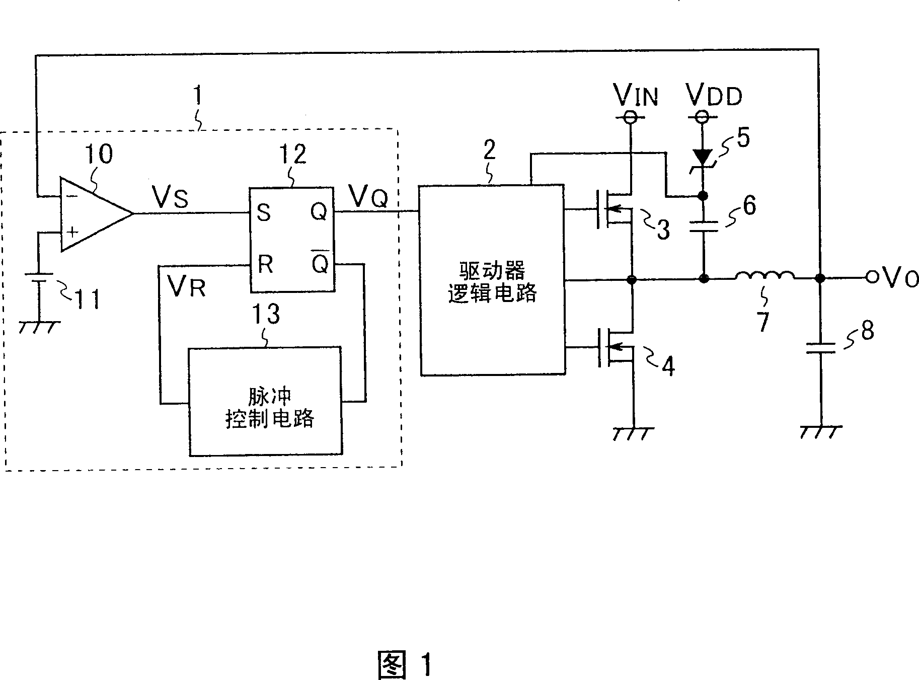
[0058] Hereinafter, embodiments of the present invention will be described with reference to the drawings. First, a first embodiment of the present invention will be described. The configuration of a switching stabilizer of a first embodiment of the present invention is shown in FIG. 1 .

[0059] The switching stabilizer shown in FIG. 1 includes a control signal generating circuit 1, a driver logic circuit 2, N-channel MOS transistors (hereinafter referred to as "NMOS" or "NMOS transistors") 3 and 4, a Zener diode 5, a capacitor 6, coil 7 and output capacitor 8 . Here, assume the input voltage V IN Ratio driving the driving voltage V of the circuit included in the control signal generating circuit 1 DD high. In this example, it is assumed that the input voltage V IN Is +25V, drive voltage V DD is +5V. In this embodiment, the NMOS 3 and 4, the coil 7 and the output capacitor together form a DC-DC converter, and the DC-DC converter converts the input voltage V IN convert...


PUM


Abstract

A control signal generating circuit (1) comprises a comparator (10) for comparing an output voltage VO with a reference voltage outputted from a reference voltage source (11), a flip-flop (12) set by the output of the comparator (10), and a pulse control circuit (13) which receives an input voltage VIN, a reference voltage VREF2, and the inverted output of the flip-flop (12), sets the on time in accordance with the ratio between the input voltage VIN and the reference voltage VREF2, and resets the flip-flop (12) when the on time elapses after the output pulse of the flip-flop (12) rises. The output pulse of the flip-flop (12) is outputted as a control signal into a driver logic circuit (2). The driver logic circuit (2) performs on/off control of NMOSs (3, 4) according to the control signal. Thus, a switching regulator capable of operating at high speed can be realized.

Description

technical field [0001] The present invention relates to switching regulators. Background technique [0002] In a conventional switching stabilizer, the error amplifier amplifies the error between the reference voltage and the voltage based on the output voltage of the switching stabilizer, and then the PWM comparator compares the output voltage of the error amplifier with a triangle wave to generate a PWM signal, and then, according to this PWM signal , to turn on or off a switching device included in the DC-DC converter (for example, see Patent Document 1 listed below). However, disadvantageously, the switching stabilizer configured as above cannot operate at high speed because the error amplifier provided in the feedback section performs an amplification operation. [0003] A current mode control switching stabilizer is an example of a switching stabilizer capable of high speed operation. In a current mode control switching stabilizer, a variable voltage shifted accordin...

Claims


Application Information

Patent Timeline
IPC IPC(8): H02M3/155
Inventor 酒井优梅本清贵蜂谷尚悟
Owner ROHM CO LTD
Why Eureka
Try Eureka