
Apparatus and methods for estimating vehicle fuel composition

A fuel composition and fuel technology, which is applied in mechanical equipment, fuel testing, combustion engines, etc., and can solve problems such as changes in stoichiometric values

Active Publication Date: 2011-12-21
GM GLOBAL TECH OPERATIONS LLC
View PDF0 Cites 0 Cited by
  • Summary
  • Abstract
  • Description
  • Claims
  • Application Information

AI Technical Summary

Problems solved by technology

However, stoichiometric values ​​may vary with fuel composition

Method used


Image

  • Apparatus and methods for estimating vehicle fuel composition
  • Apparatus and methods for estimating vehicle fuel composition
  • Apparatus and methods for estimating vehicle fuel composition

Examples


Embodiment Construction

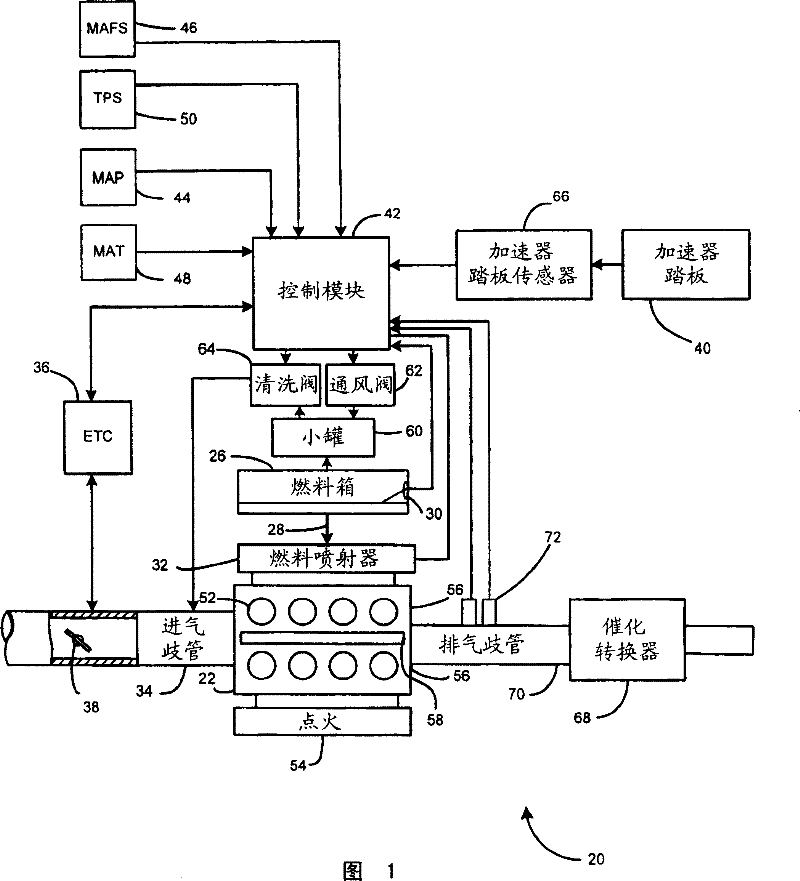
[0014] The following descriptions of various embodiments of the invention are merely exemplary in nature and are not intended to limit the invention, its application or uses. For clarity, the same reference numerals in the drawings refer to the same parts. As used herein, the terms "module" and / or "device" refer to an application-specific integrated circuit (ASIC), electronic circuit, processor (shared, dedicated, or grouped) and Combinational logic circuits of the device program, and / or other suitable modules providing the described functionality.

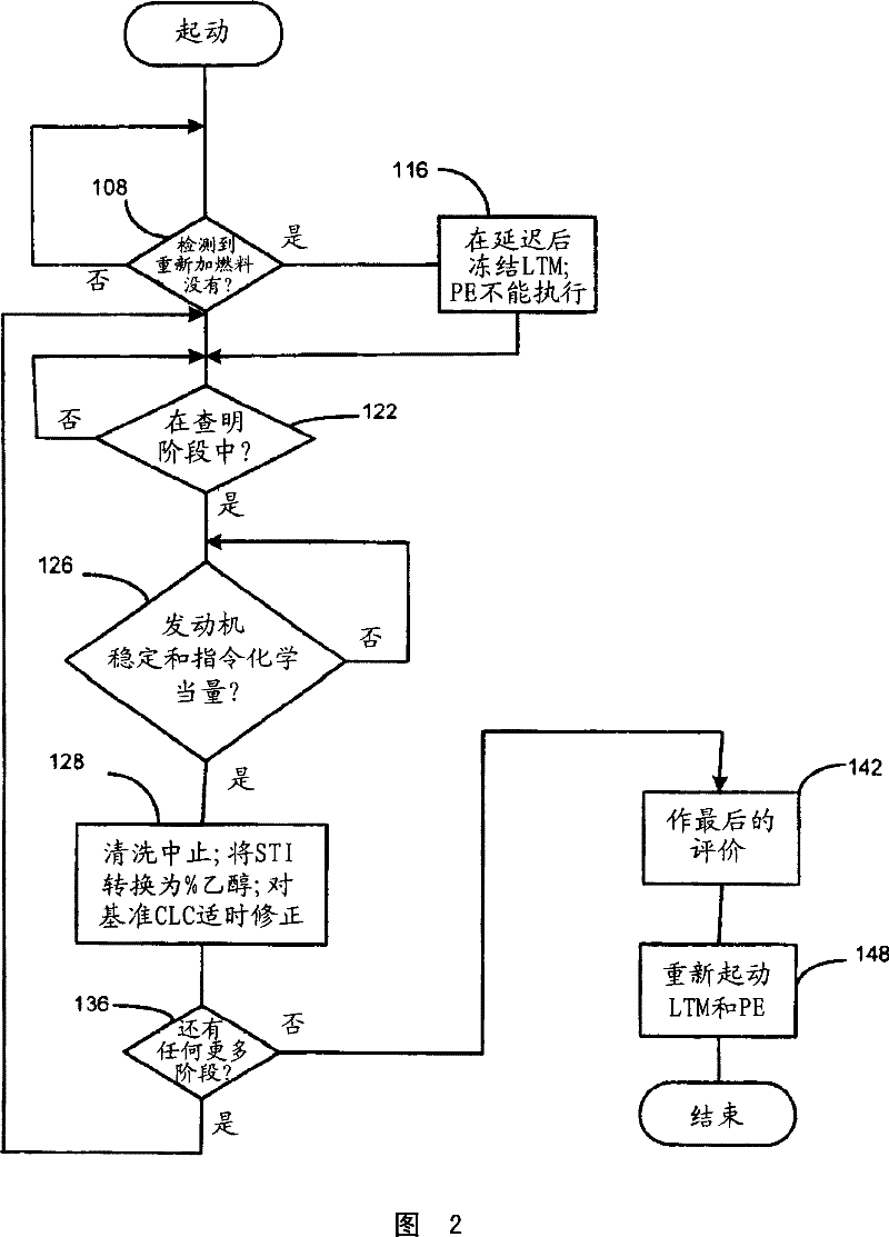
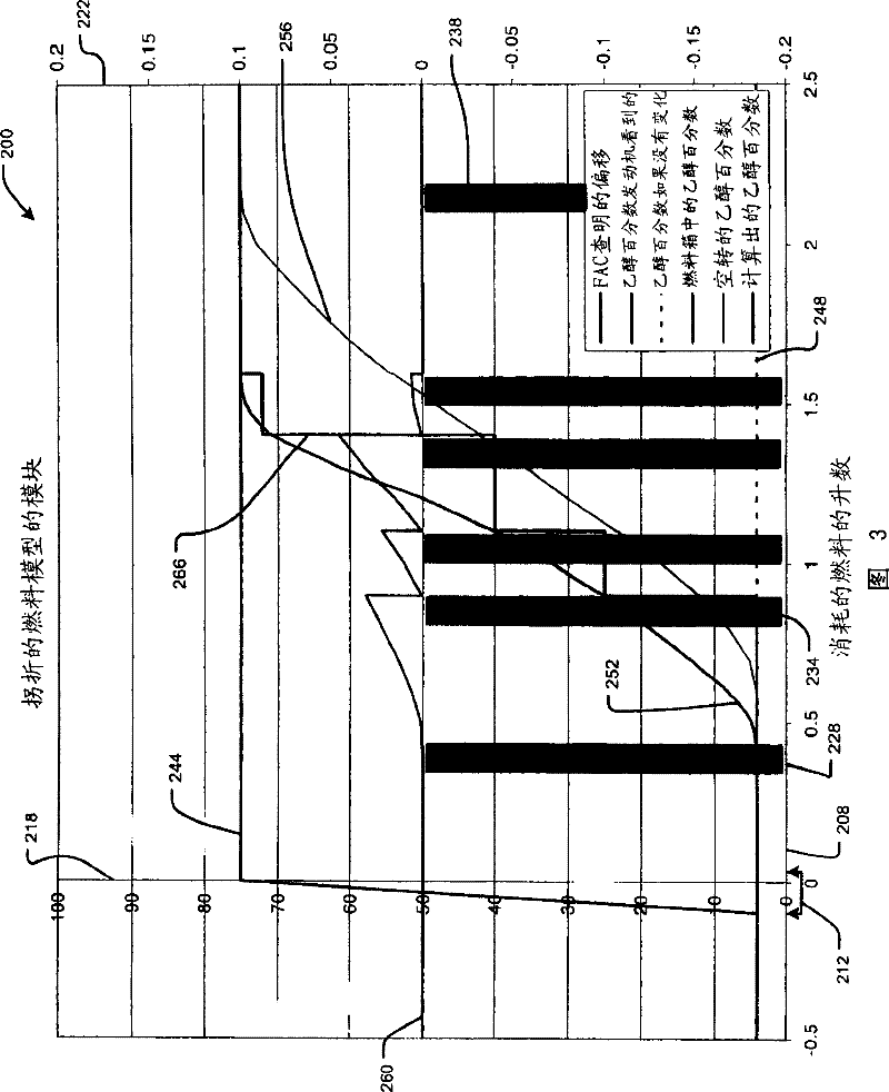
[0015] In one embodiment, the present invention is directed to a method for evaluating the relative amounts of fuel components, such as ethanol and gasoline, in a fuel tank of a vehicle. Typically, when the vehicle is refueled, the transition between the existing and new fuel compositions occurs at a nominally fixed speed determined as a function of fuel consumed. It can thus be discerned from fuel system failures which usually ...


PUM


Abstract

A method of estimating composition of fuel in the fuel tank of a vehicle. A refuel event is detected. Fuel consumption is monitored during a plurality of stages after the refuel event. A plurality of fuel trim shift values are determined relative to the stages. The fuel trim shift values are used to estimate a fuel composition change. This method eliminates a need for a hardware fuel composition sensor and also provides dynamic filtering of fuel trim values.

Description

technical field [0001] The present invention relates generally to vehicle fuel control, and more particularly to systems and methods for evaluating fuel composition in a vehicle's fuel tank. Background technique [0002] Closed loop fuel control systems are commonly used in gasoline powered vehicles to maintain the operating air-to-fuel (A / F) ratio at stoichiometric. However, stoichiometric values ​​may vary with fuel composition. For example, when fuel is added to a vehicle's fuel tank, it mixes with the fuel already in the tank. For example, ethanol or "gasohol" in varying mix ratios can be added to gasoline already in the tank. If the added fuel has a different composition than the fuel already in the tank, the vehicle's engine may operate at a different stoichiometry after refueling. Currently manufactured vehicles may include a hardware sensor that senses the ethanol content in the fuel and communicates it with other systems in the vehicle. Contents of the inventio...

Claims


Application Information

Patent Timeline
Patent Type & Authority Patents(China)
IPC IPC(8): G01N33/22G06F19/00
CPCY02T10/36F02D41/0032F02D19/0665F02D19/0628F02D19/061F02P5/1527F02D19/084F02D19/088Y02T10/30
Inventor M·D·卡尔J·R·杜尔佐C·R·格拉汉R·B·杰斯I·J·马塞温O·马休斯J·A·塞尔M·J·斯维斯特卡J·R·费尔德约
Owner GM GLOBAL TECH OPERATIONS LLC
Learn More