Plasma display panel

A display panel, plasma technology, applied to AC plasma display panels, sustain/scan electrodes, electrical components, etc., can solve problems such as uneven discharge diffusion, reduced discharge efficiency, and reduced brightness, and achieve smooth discharge diffusion and increased discharge efficiency. , the effect of increasing the number of discharges

Inactive Publication Date: 2007-03-28
NANJING LG TONGCHUANG COLOR DISPLAYS SYST CO LTD
View PDF0 Cites 0 Cited by
  • Summary
  • Abstract
  • Description
  • Claims
  • Application Information

AI Technical Summary

Problems solved by technology

[0010] As mentioned above, in the plasma display panel in the prior art, in order to make the discharge starting from the above-mentioned certain gap (GAP) diffuse effectively into the entire discharge cell (cell), the initial stage of the discharge should be carried out in a wider area , when the above-mentioned certain gap (GAP) is formed at a certain pitch, the initial stage of the discharge is carried out in the local area, so the diffusion of the discharge is not smooth
[0011] That is, when a voltage is negat

Method used


Image

  • Plasma display panel
  • Plasma display panel
  • Plasma display panel

Examples


Embodiment Construction

[0033] Hereinafter, preferred embodiments are given, and detailed descriptions are given in conjunction with the accompanying drawings.

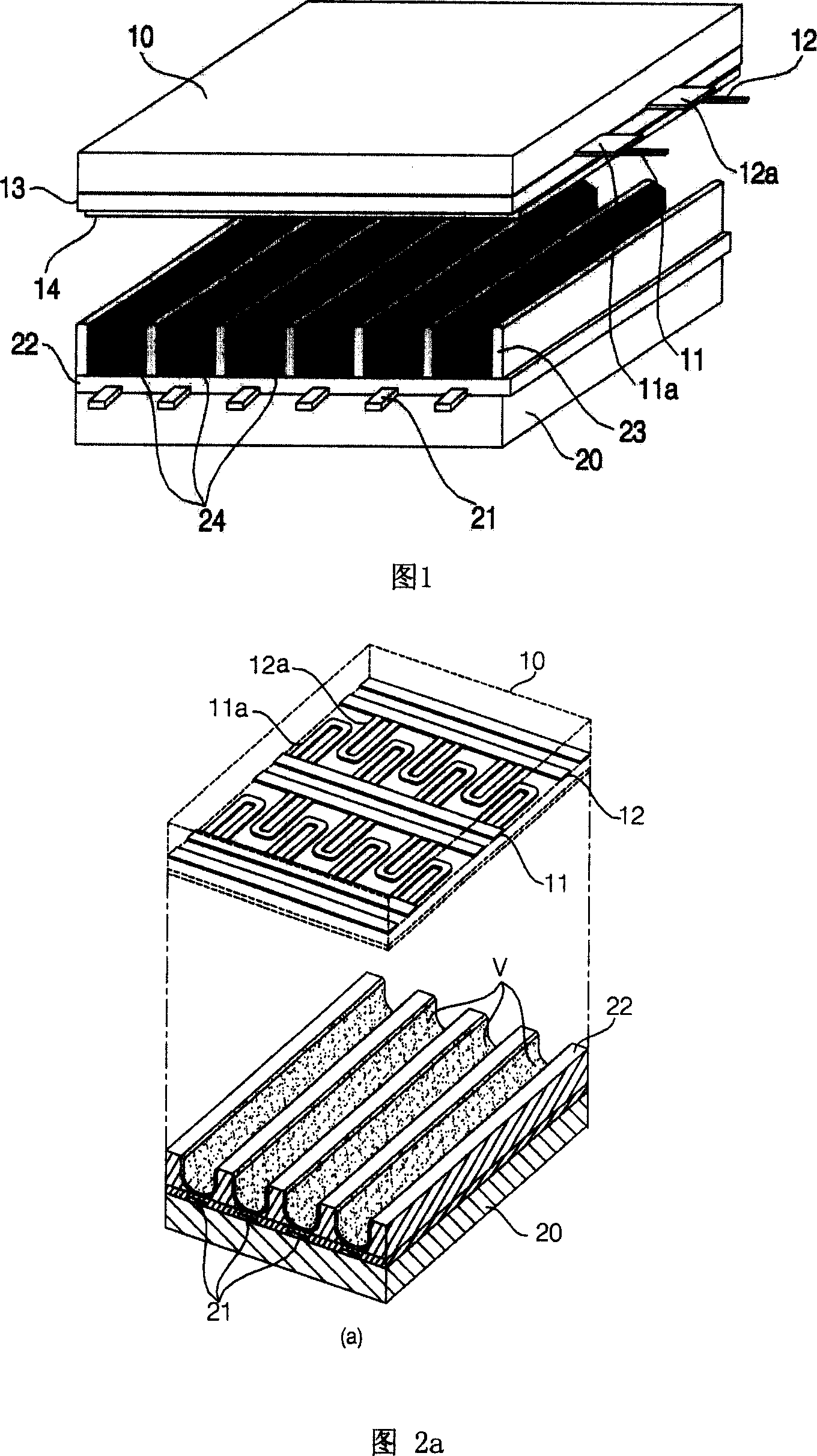
[0034] FIG. 1 is a schematic structural diagram of a plasma display panel in the present invention. The scan electrodes and the sustain electrodes of the above-mentioned plasma display panel should be arranged in units of discharge cells (cells), but for convenience, only one scan electrode and one sustain electrode are shown in the figure.

[0035] The plasma display panel in the present invention is composed of a front substrate 10 and a rear substrate 20 as shown in FIG. 1 .

[0036] At this time, the scan electrodes 11 and the sustain electrodes 12 are formed on the front substrate 10 , and the first dielectric layer 13 should be accumulated adjacent to the scan electrodes 11 and the sustain electrodes 12 . In addition, a dielectric protection layer 14 for protecting the above-mentioned first dielectric layer 13 may also be included.

...


PUM

PropertyMeasurementUnit
Lengthaaaaaaaaaa

Abstract

Disclosed is a plasma display panel, which includes a back base plate formed into a plurality of orientation electrodes and the interlayers, and a front base plate opposed to the back base plate to form into a plurality of sweeping electrodes and the maintaining electrodes. The sweeping auxiliary electrode and the maintaining auxiliary electrodes are formed between the sweeping electrodes and the maintaining electrodes. The sweeping auxiliary electrode and the maintaining auxiliary electrodes extrude alternately from the opposite electrodes of the sweeping electrodes and the maintaining electrodes, thereby, the initial discharge voltage of the plasma display panel is reduced and the time jitter characteristic of the electron liberation is reduced when the plasma discharges. At the same time, the number of the discharge is increased, and the discharge diffuse is comparatively smooth in the discharge field to advance the discharge efficiency, thereby, the brightness in the discharge cell is increased.

Description

1. Technical field [0001] The present invention relates to a plasma display panel, specifically, a scanning auxiliary electrode / sustaining auxiliary electrode is formed between the scanning electrode / sustaining electrode, and each auxiliary electrode formed alternates from the scanning electrode and the sustaining electrode to the opposite electrode. Protruding plasma display panel. 2. Background technology [0002] A general plasma display panel (Plasma Display Panel, hereinafter referred to as PDP) uses vacuum ultraviolet rays (VUV) released by plasma generated during gas discharge to excite phosphors to produce red (R), green (G), blue (B) Visible light, a display element that displays a certain image. [0003] As mentioned above, PDP can display a super-large screen of more than 60 inches with a display device with a thickness of less than 10 cm, and because it is a self-luminous display element like a CRT, it has the characteristics of color display and no distortion o...

Claims


Application Information

Patent Timeline
IPC IPC(8): H01J17/04H01J17/49H01J11/28
CPCH01J11/12H01J11/24H01J11/28H01J11/32H01J2211/245H01J2211/323
Inventor 李相国
Owner NANJING LG TONGCHUANG COLOR DISPLAYS SYST CO LTD
Why Eureka
Try Eureka