Stepless speed changer

A technology of continuously variable transmission and speed change mechanism, applied in the direction of transmission parts, friction transmission, belt/chain/gear, etc., can solve the problems of affecting the transmission accuracy of rotation speed, affecting the accuracy of connecting gears, affecting the quality of fabrics, etc. Operational performance and accuracy, improved delivery accuracy, and improved quality effects

Inactive Publication Date: 2007-04-04
NIDEC SHIMPO CORP
View PDF1 Cites 85 Cited by
  • Summary
  • Abstract
  • Description
  • Claims
  • Application Information

AI Technical Summary

Problems solved by technology

[0006] However, as mentioned above, if the output shaft of the continuously variable transmission is connected to the rotating shaft of the driven part through the transmission belt, the transmission of the rotational speed will be affected due to the micro vibration generated on the transmission belt or the slippage of the transmission belt. Accuracy, in turn, may produce defects (woven segments) that affect fabric quality
[0007] In addition, in the past, the ou...

Method used


Image

  • Stepless speed changer
  • Stepless speed changer
  • Stepless speed changer

Examples


Embodiment Construction

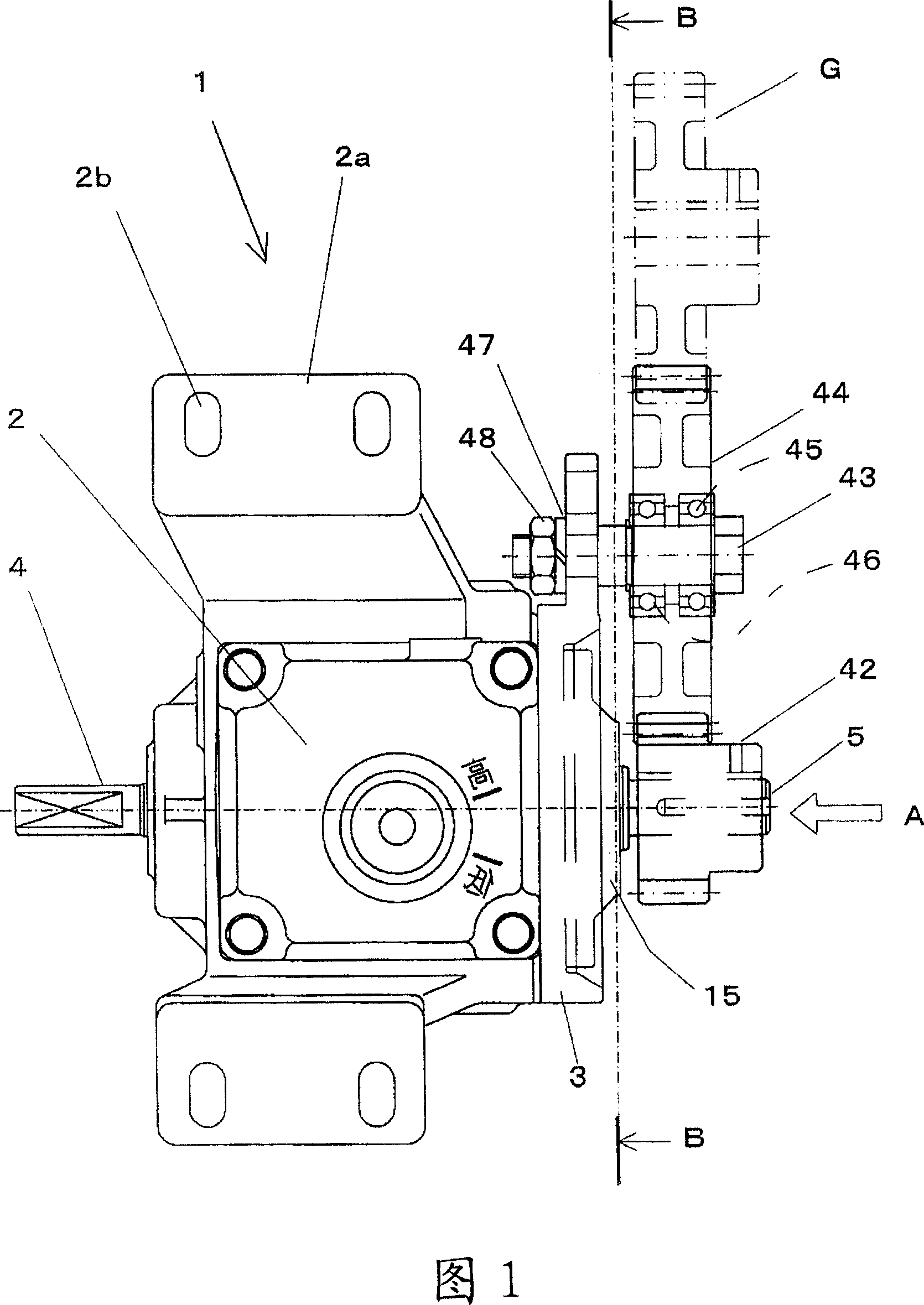
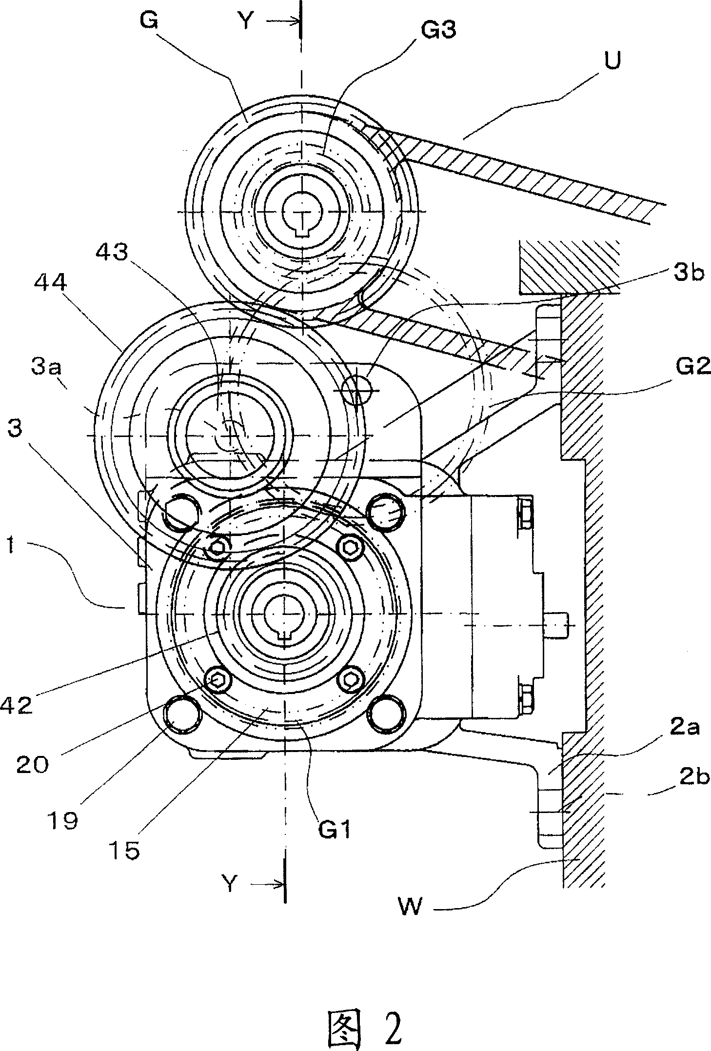
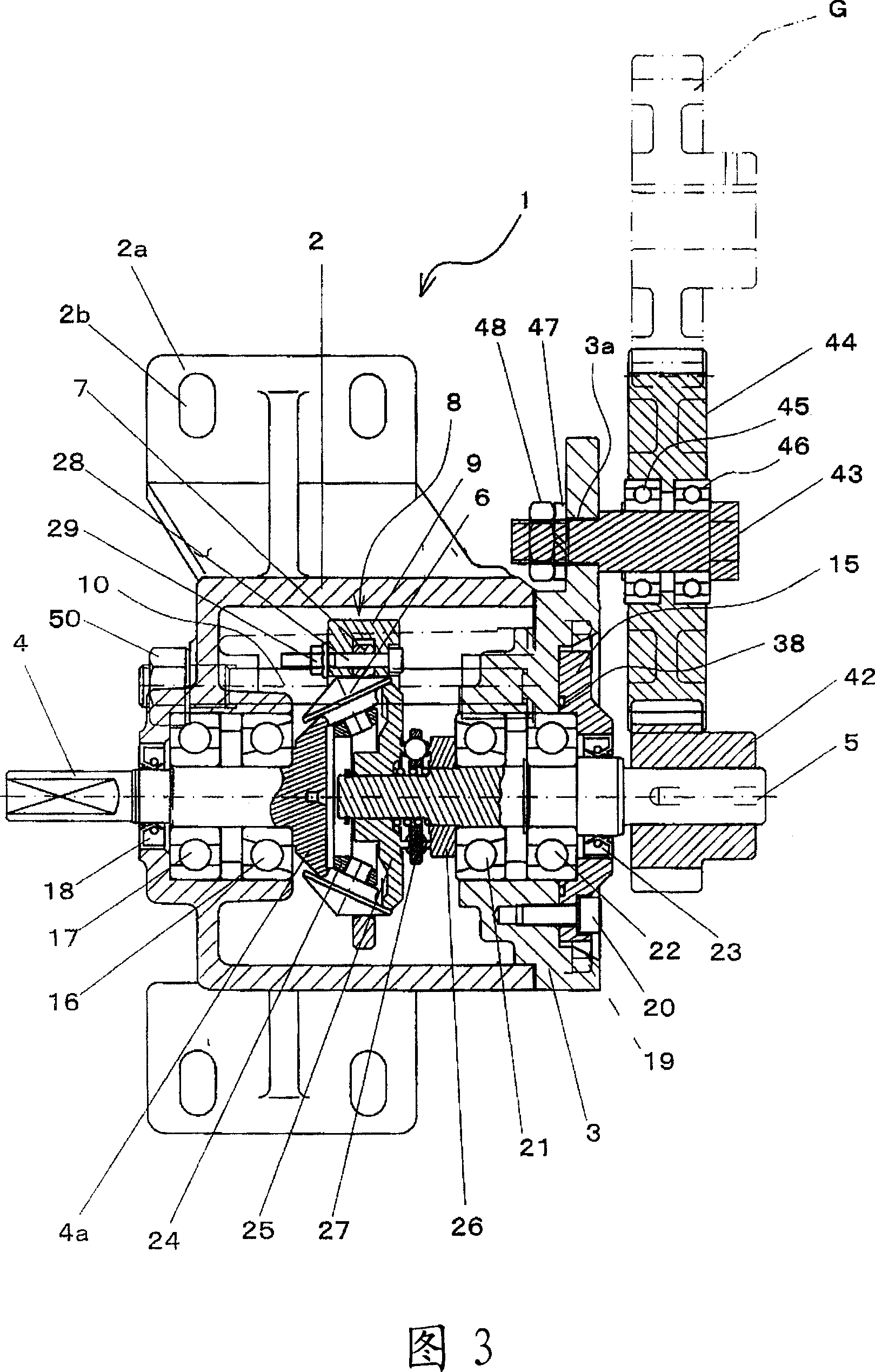
[0027] Next, an embodiment of the continuously variable transmission of the present invention will be described with reference to the drawings. Fig. 1 is the exterior view that has shown the overall structure of the continuously variable transmission that has used an embodiment of the present invention; Fig. 2 is the exterior view of the continuously variable transmission of the above-mentioned embodiment represented from the arrow A direction in Fig. 1; Fig. 3 is The sectional view of the continuously variable transmission of the above-mentioned embodiment along the arrow Y-Y in Fig. 2; Fig. 4 is the partial sectional view of the continuously variable transmission of the above-mentioned embodiment along the arrow B-B direction in Fig. 1; A cross-sectional view of the speed change mechanism in the continuously variable transmission of the embodiment; FIG. 6 is an explanatory diagram of the speed change operation in the continuously variable transmission of the above embodiment....


PUM


Abstract

The present invention provides a gearless drive mechanism, facilitating the connection between an output shaft of a continuously variable transmission and a rotating shaft of a driven body, and transmitting the rotating speed of the output shaft to the rotating shaft of the driven body with good accuracy. The gearless drive mechanism includes: an input shaft 4 rotating on receiving the driving force; an output shaft 5, one end of which is connected to the input shaft through a variable speed mechanism, the other end being projected from a casing; a first gear 42 disposed outside the casing 3 to be spline-coupled to the projecting part of the output shaft 5 and rotated in a body with the output shaft 5; and a second gear 44 rotatablely supported on the casing 3 through a support shaft 43 to mesh with the first gear 42.

Description

technical field [0001] The present invention relates to a continuously variable transmission that changes the rotational speed of a driving source, and in particular to a loom that is rotated by the driving force of a drive motor and that changes the rotational speed of a warp shaft around which warp yarns are wound according to the tension of warp yarns CVT. Background technique [0002] Conventionally, there is known a continuously variable transmission having a structure in which an input shaft and an output shaft are provided in a housing, and the driving force of the output shaft is transmitted to a driven member, and the input shaft is rotated by the driving force of the driving motor. , one end of the output shaft is connected to the above-mentioned input shaft through a transmission mechanism, and the other end protrudes from the above-mentioned housing. [0003] In addition, in the past, in the loom, the drive part that sends out warp yarn has following stepless tr...

Claims


Application Information

Patent Timeline
IPC IPC(8): F16H15/00F16H15/52F16H57/021
Inventor 若松俊男毛利哲德
Owner NIDEC SHIMPO CORP
Why Eureka
Try Eureka