


Quick Research
Generate reliable direction feasibility study reports for your R&D in just a few steps.

Technical Q&A
Discover and master advanced knowledge NOW. Basics, ideas, possibilities, all at once.

Find Solutions
As an expert in R&D theories, this can generate solutions to your technical problems instantly.

Evaluate Feasibility
Analyze your overall solution with one click, know your potential R&D risks in advance.

Monitor Landscape
Get weekly tech updates, stay abreast of the latest tech innovations and key insights.
Image display apparatus and light source unit
A technology of an image display device and a light source device, which is applied in projection devices, image communication, optics, etc., can solve the problems of large-scale overall devices and high costs, and achieve the effect of small size
- Summary
- Abstract
- Description
- Claims
- Application Information
AI Technical Summary
Problems solved by technology
Method used
Image

Examples
no. 1 Embodiment approach
[0051] First, a first embodiment of the present invention will be described with reference to FIGS. 1 and 2 .
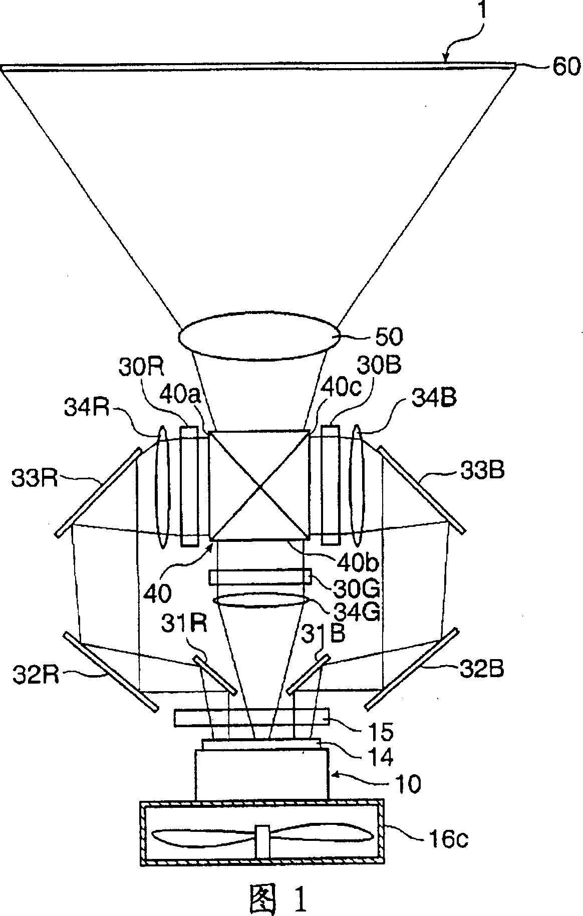
[0052] As the image display device of the present embodiment, as shown in FIG. 1 , a projector 1 that projects light corresponding to an image signal onto a screen 60 will be described as an example.
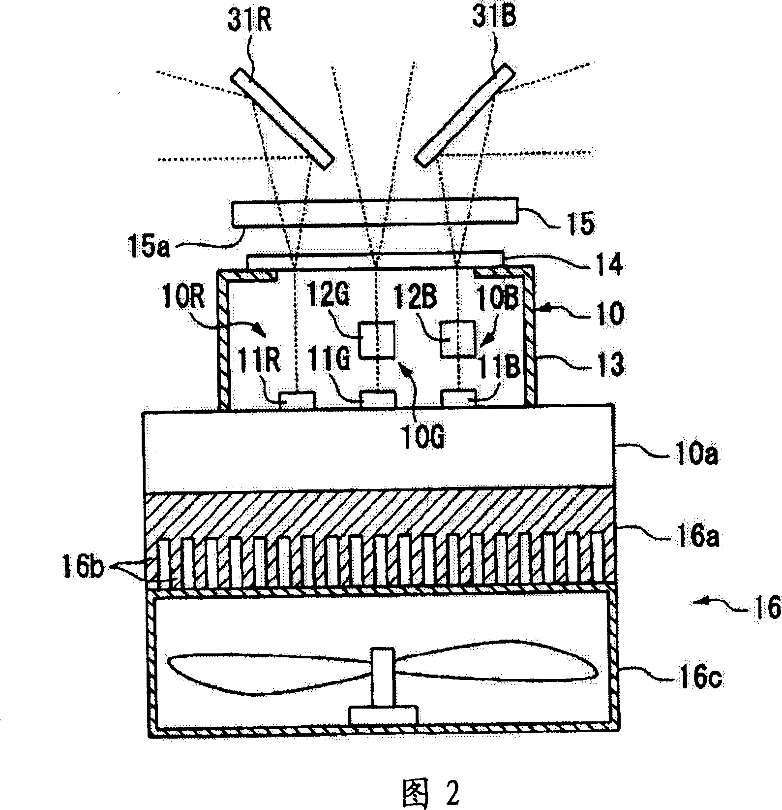
[0053] The projector 1, as shown in FIG. 1 and FIG. 2 , includes: a light source device 10 having a light source device 10R for emitting red light (hereinafter referred to as "R light") for emitting red light (hereinafter referred to as "R light") and a light source device 10R for emitting green light ( Hereinafter, referred to as "G light.") light source device 10G for G light and light source device 10B for B light emitting blue light (hereinafter referred to as "B light"); a plurality of transmissive liquid crystal light valves (light modulation Devices: liquid crystal panels (hereinafter referred to as liquid crystal light valves) 30R, 30G, and 30B that respectivel...
no. 2 Embodiment approach
[0071] Next, a second embodiment of the present invention will be described with reference to FIG. 3 . In addition, in each embodiment described below, the same code|symbol is attached|subjected to the same structure as the projector 1 of 1st Embodiment mentioned above, and description is abbreviate|omitted.
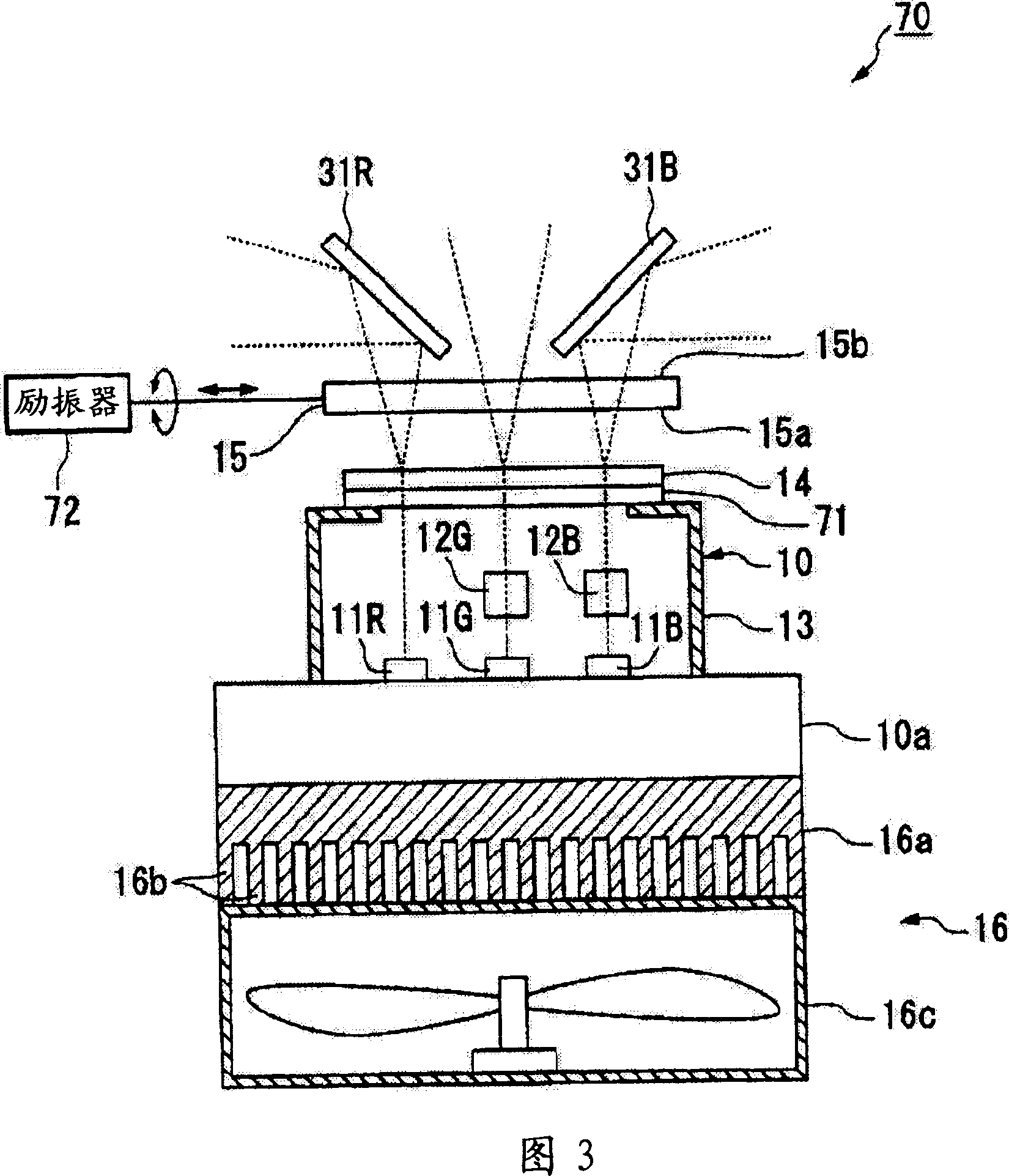
[0072] In the projector 70 of this embodiment, the second embodiment differs from the first embodiment in that an infrared cut filter 71 is provided.
[0073]Infrared cutoff filter 71, as shown in FIG. 3, is fixed to block the opening 13a of housing 13; The side opposite to the side of 11G and 11B. The infrared cut filter 71 transmits visible light (about 380 to about 780nm), and blocks infrared light (about 780nm). Homogenize.
[0074] In addition, the light diffusing plate 15 is provided with an exciter 72 that changes the diffusion state of the laser light incident from the incident surface 15 a and emitted from the emitting surface 15 b of the light diffusing plat...
no. 3 Embodiment approach
[0079] Next, a third embodiment of the present invention will be described with reference to FIG. 4 .
[0080] FIG. 4( a ) is a plan view of the projector 80 of this embodiment; FIG. 4( b ) is a side view of the projector 80 of this embodiment.
[0081] The projector 80 of this embodiment differs from the first embodiment in that the optical path lengths between the illuminance equalizing element 14 and the liquid crystal light valves 30R, 30G, and 30B are all the same in the third embodiment.
[0082] In the projector 80 , as shown in FIGS. 4( a ) and ( b ), the optical paths of the R light and the B light are bent in the horizontal plane, and only the optical path of the G light is bent in the vertical plane. Specifically, the projector 80 includes: a first mirror 81 that converts the optical path of light emitted from the laser light source 11G by 90 degrees, and a second mirror that reflects the light reflected by the first mirror in the direction of the liquid crystal lig...
PUM
| Property | Measurement | Unit |
|---|---|---|
| wavelength | aaaaa | aaaaa |
| wavelength | aaaaa | aaaaa |
Abstract
Description
Claims
Application Information
 - R&D Engineer
- R&D Manager
- IP Professional
- Industry Leading Data Capabilities
- Powerful AI technology
- Patent DNA Extraction
Browse by: Latest US Patents, China's latest patents, Technical Efficacy Thesaurus, Application Domain, Technology Topic, Popular Technical Reports.
© 2024 PatSnap. All rights reserved.Legal|Privacy policy|Modern Slavery Act Transparency Statement|Sitemap|About US| Contact US: help@patsnap.com