Design method for permanent magnet bias inner rotor radial mixed magnetic bearing

A radial hybrid, permanent magnet bias technology, applied in the direction of bearings, shafts and bearings, mechanical equipment, etc., can solve the problems of difficult processing, small size of permanent magnets, poor accuracy, etc.

Inactive Publication Date: 2007-04-11
BEIHANG UNIV
View PDF0 Cites 5 Cited by
  • Summary
  • Abstract
  • Description
  • Claims
  • Application Information

AI Technical Summary

Problems solved by technology

The existing magnetic bearing design methods all use the best working point of the permanent magnet to design, the purpose is to minimize the volume of the permanent magnet, but the size of the permanent magnet calculated by this method will be small, and the processing will be very difficult. The method does not consider the influence of the displacement stiffness on the control system, so the existing design methods have the defects of poor accuracy and unfavorable control
What needs to be explained here is that the design ideas of the inner rotor magnetic bearing and the outer rotor magnetic bearing are different. For the inner rotor structure, the idea is to design the magnetic bearing rotor assembly first, and then design the stator assembly (including the permanent magnet); for the outer rotor magnetic Bearings, first design the magnetic bearing stator assembly, and then design the magnetic bearing rotor assembly (including permanent magnets), and the magnetic circuit structure of the inner rotor radial hybrid magnetic bearing and the outer rotor magnetic bearing with different structures is completely different, so it cannot be simple Apply the design method of outer rotor magnetic bearing to the design of inner rotor magnetic bearing

Method used


Image

  • Design method for permanent magnet bias inner rotor radial mixed magnetic bearing
  • Design method for permanent magnet bias inner rotor radial mixed magnetic bearing
  • Design method for permanent magnet bias inner rotor radial mixed magnetic bearing

Examples


Embodiment Construction

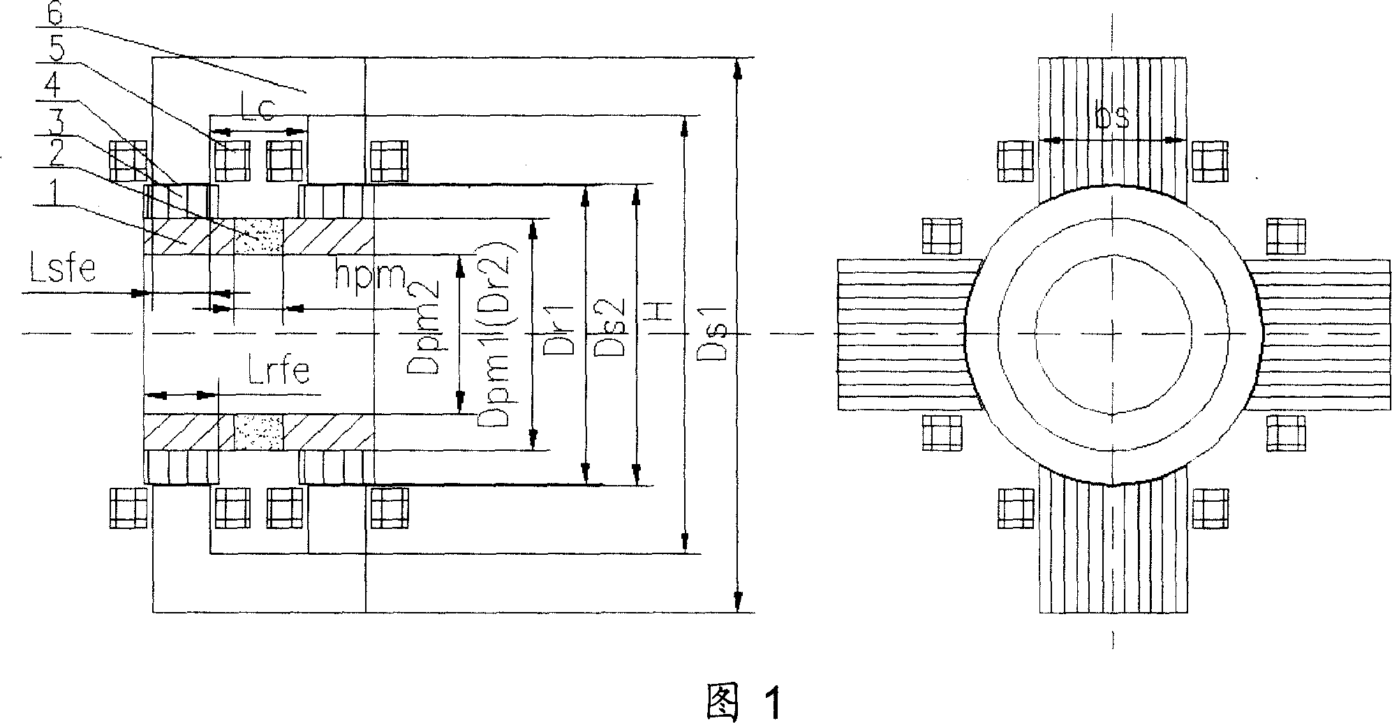
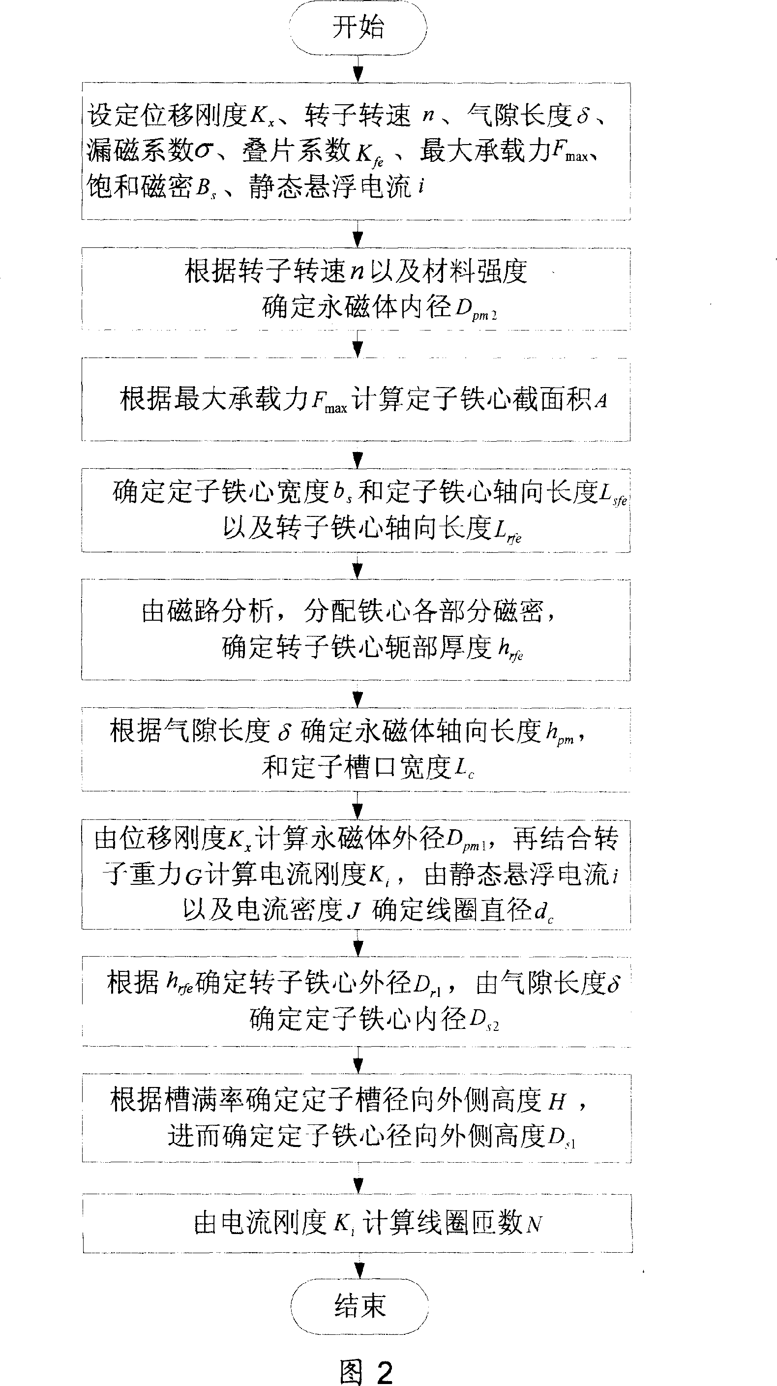
[0051] As shown in Figure 1, the design object of the present invention is a permanent magnetic bias inner rotor radial hybrid magnetic bearing for a magnetic levitation control moment gyroscope, in which 1 is a magnetic ring, 2 is a permanent magnet, 3 is a rotor core, 4 is the magnetic air gap between the stator and rotor, 5 is the coil, and 6 is the stator core. Set the displacement stiffness K of the magnetic bearing according to the requirements of the existing magnetic bearing controller x -0.8N / um, set the rotor speed n as 30000r / min according to the requirements of the maglev control torque gyro index, and then set the permanent magnet inner diameter D according to the material strength pm2 19mm, set the air gap length δ as 0.2mm according to the existing processing level, and the lamination coefficient K fe is 0.85, according to the magnetic field analysis of the magnetic bearing, the magnetic leakage coefficient σ is set to 1.2, and the maximum bearing capacity F is...


PUM


Abstract

The design method of mixed magnetic bearing with permanent magnetic bias inner rotor has the displacement rigidity of the magnetic bearing as main consideration, and the maximum bearing capacity, saturation magnetic induction and tankful rate as restraint conditions. Compared with available design method with optimal work point of the permanent magnet as target, the method of the present invention has the advantages of easy control of magnetic bearing, reasonable permanent magnet size, high accuracy, and being simple and practical. The design philosophy of the present invention may be used in design of different kinds of mixed magnetic bearing with permanent magnetic bias inner rotor.

Description

technical field [0001] The invention relates to a design method of a non-contact magnetic suspension bearing, in particular to a design method of a permanent magnetic bias inner rotor radial hybrid magnetic bearing for a magnetic suspension flywheel, a magnetic suspension control moment gyroscope, and other devices that require magnetic suspension support. As a design for various types of permanent magnet bias inner rotor radial hybrid magnetic bearings. Background technique [0002] Magnetic suspension bearings are divided into pure electromagnetic bearings and hybrid magnetic suspension bearings with permanent magnetic bias and electromagnetic control. The former uses large current and consumes a lot of power, and the hybrid magnetic suspension bearings with permanent magnetic bias and electromagnetic control. The magnetic field generated by the permanent magnet bears the main load. Bearing capacity, the electromagnetic field provides auxiliary adjustment bearing capacity,...

Claims


Application Information

Patent Timeline
Patent Type & Authority Applications(China)
IPC IPC(8): F16C32/04
CPCF16C32/0468F16C32/0487
Inventor 孙津济房建成韩邦成王曦
Owner BEIHANG UNIV
Why Eureka
Try Eureka