Projection display device

A projection display and projection lens technology, applied in projection devices, TVs, color TVs, etc., can solve problems such as high production costs, complicated manufacturing processes, brightness, and image quality degradation, and achieve the effect of easier production and mass production

Inactive Publication Date: 2007-04-11
HONG FU JIN PRECISION IND (SHENZHEN) CO LTD +1
View PDF0 Cites 3 Cited by
  • Summary
  • Abstract
  • Description
  • Claims
  • Application Information

AI Technical Summary

Problems solved by technology

[0004] The micromirror projector 100 needs to realize color image display through the cooperation of multiple micromirrors and the color wheel 106. Its structure is relatively complicated, which leads to its complicated manufacturing process

Method used


Image

  • Projection display device
  • Projection display device
  • Projection display device

Examples


Embodiment Construction

[0013] The present invention will be further described in detail below in conjunction with the accompanying drawings.

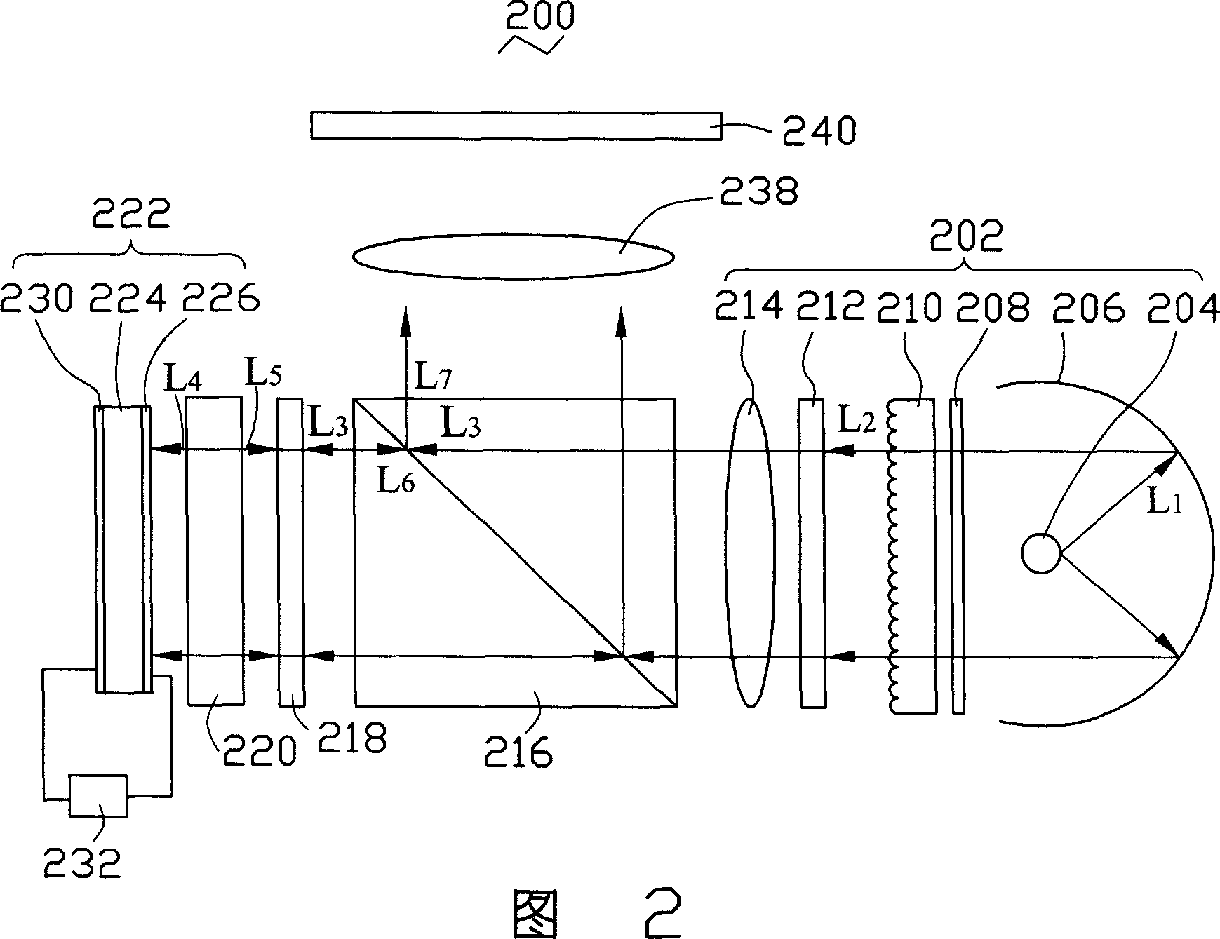
[0014] As shown in FIG. 2 , it is the first embodiment of the projection display device of the present invention. The projection display device 200 includes a white flat light source module 202, a polarizing beam splitter (Polarizing Beam Splitter, PBS) 216, a quarter-wave plate (Quarter-wave Plate) 218, a light-transmitting plate 220, a The piezoelectric ceramic body 222 , a controller 232 and a projection lens (Projection Lens) 238 . The planar light source module 202 , the polarizing beam splitter 216 , the quarter wave plate 218 , the transparent plate 220 and the piezoelectric ceramic body 222 are sequentially arranged along the same axis. The projection lens 238 is facing the polarizing beam splitter 216 and is arranged in a direction perpendicular to the axis.

[0015] The planar light source module 202 includes a light source 204, a reflector 206, a...


PUM


Abstract

This invention relates to a projecting display device. The device includes a white planar light source module, a translucent panel and a piezoelectric ceramic. There is an electrode-array on each of the two relative surfaces of the piezoelectric ceramic, and the electrodes are placed in the two electrode-arrays in one to one correspondence. One of the electrode-array faces the source module, and each electrode in the array has a reflective surface, and the reflective surface is used to reflect the white single polarized reflectance from the source module. One controller provides a predetermined voltage on the two corresponding electrodes to change the space between the two reflective surfaces to create a destructive interference of one kind of color and the scheduled colors.

Description

【Technical field】 [0001] The present invention relates to a projection display device, in particular to a projection display device for displaying color images. 【Background technique】 [0002] A projection display device is a device that uses an optical system and a projection space to magnify and display a light-emitting image controlled by information on a screen. As shown in FIG. 1 , it is a projection display device 100 for displaying color images in the prior art. The projection display device 100 includes a light source 102 , a converging lens 104 , a color wheel (Color Wheel) 106 , a trimming lens 108 , a micromirror chip 110 and a projection lens group 112 . [0003] The color wheel 106 includes a red zone 1062 , a green zone 1064 and a blue zone 1066 . The color wheel 106 is in the shape of a disk, and the color wheel 106 is rotated around its center at a high speed by a mechanical method. The light emitted by the light source 102 is converged by the converging le...

Claims


Application Information

Patent Timeline
IPC IPC(8): G02B27/18G03B21/20H04N5/74H01L41/00
Inventor 张仁淙
Owner HONG FU JIN PRECISION IND (SHENZHEN) CO LTD
Why Eureka
Try Eureka