Electric pneumatic type machine for assembling U-shaped ribs of plate units

A pneumatic, single-component technology, applied in metal processing, metal processing equipment, manufacturing tools, etc., can solve the problems of inability to apply other shapes of rib assembly, labor intensity of workers, long operation time, etc., to reduce labor costs and Uptime, smooth and reliable transmission, long life effect

Active Publication Date: 2007-04-18
WUCHUAN HEAVY ENG
View PDF0 Cites 12 Cited by
  • Summary
  • Abstract
  • Description
  • Claims
  • Application Information

AI Technical Summary

Problems solved by technology

[0003] Aiming at the problems that the current manual U-shaped rib assembly machine has high labor intensity, long operation time, low precision and cannot be applied to other shapes of rib assembly, the present invention provides a U-shaped rib assembly machine, which can not only greatly reduce the The labor intensity of the workers, and the operation time is short, the precision is high, and it can be easily applied to the assembly of ribs of different shapes

Method used


Image

  • Electric pneumatic type machine for assembling U-shaped ribs of plate units
  • Electric pneumatic type machine for assembling U-shaped ribs of plate units
  • Electric pneumatic type machine for assembling U-shaped ribs of plate units

Examples


specific Embodiment approach 1

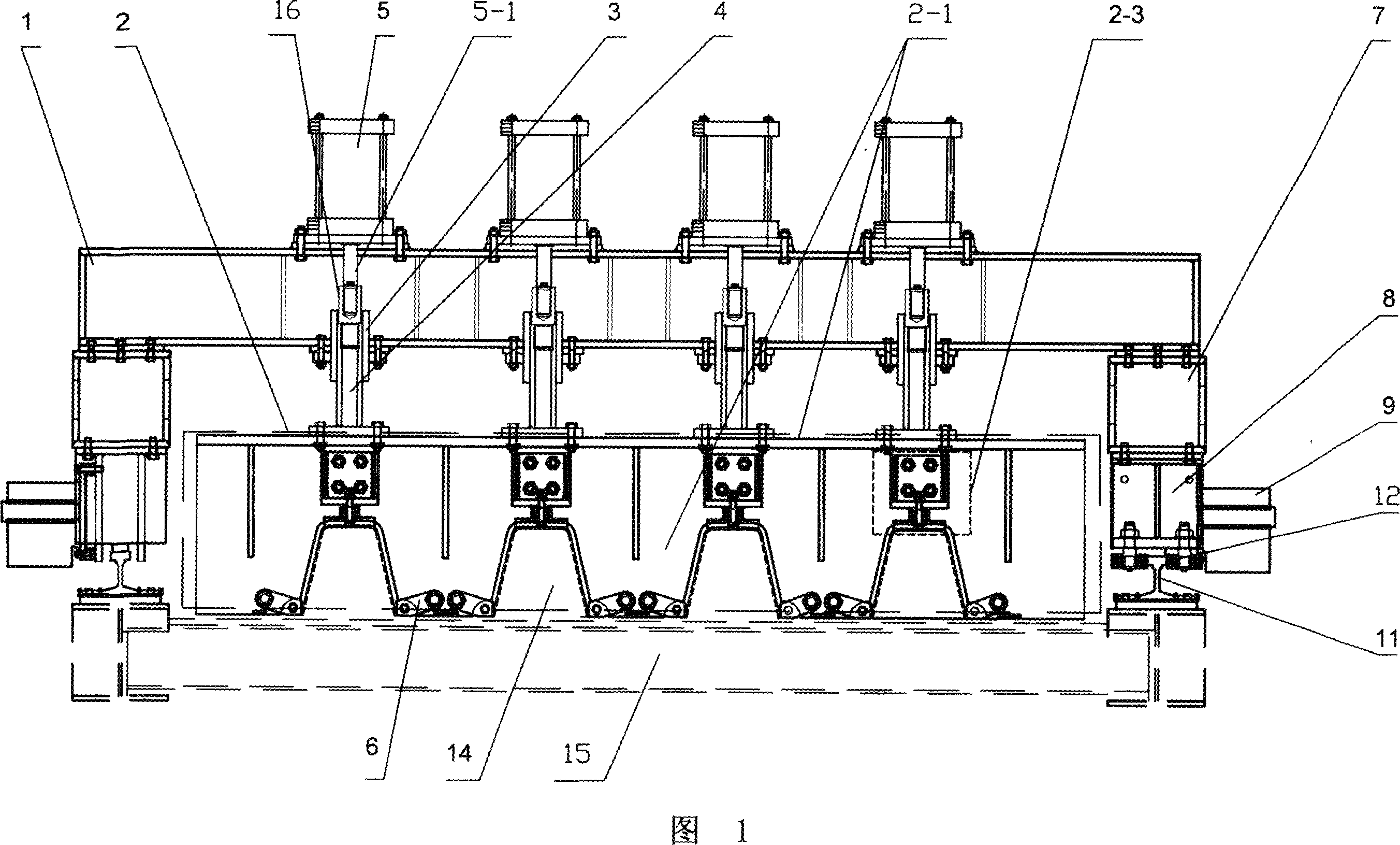
[0011] Specific Embodiment 1: This embodiment is an electro-pneumatic plate unit element U-shaped rib assembly machine, which includes a beam 1 and a formwork assembly 2 arranged below the beam 1. The formwork assembly 2 includes a formwork 2-1 and is arranged on the 2-1 The positioning block 6 at the lower end, there are at least two positioning blocks 6 and they are respectively arranged on both sides of the U-shaped rib to be assembled. The length of the positioning block 6 depends on the shape of the rib to be processed and the distance between the rib and the rib. Determined by the distance, the positioning block 6 is hinged to the template 2-1. A guide sleeve 3 is fixed on the crossbeam 1, and a guide rod 4 is arranged in the guide sleeve 3, and the lower end of the guide rod 4 is connected with the template assembly 2 by bolts. platform, the boss and the template 2-1 can be connected by bolts; the cylinder 5 is fixed on the beam 1, and the lower end of the piston rod 5-...

specific Embodiment approach 2

[0014] Embodiment 2: The formwork assembly 2 in this embodiment also includes an elastic platen device 2-3 fixed on the formwork 2-1, and the elastic platen device 2-3 includes a platen seat 2-3- 1. The rubber spring 2-3-2 and the pressure plate 2-3-3 are connected by bolts. The rubber spring 2-3-2 is set on the elastic platen device, which can compensate the U-shaped rib with height error without causing the U-shaped rib to be deformed under pressure, so that the assembly accuracy can be improved and the Damage to cylinders or other components due to inaccurate pressure control. The rubber spring in this embodiment can also be replaced by a metal spring, both of which can achieve the above purpose, and therefore all fall within the protection scope of the present invention.

specific Embodiment approach 3

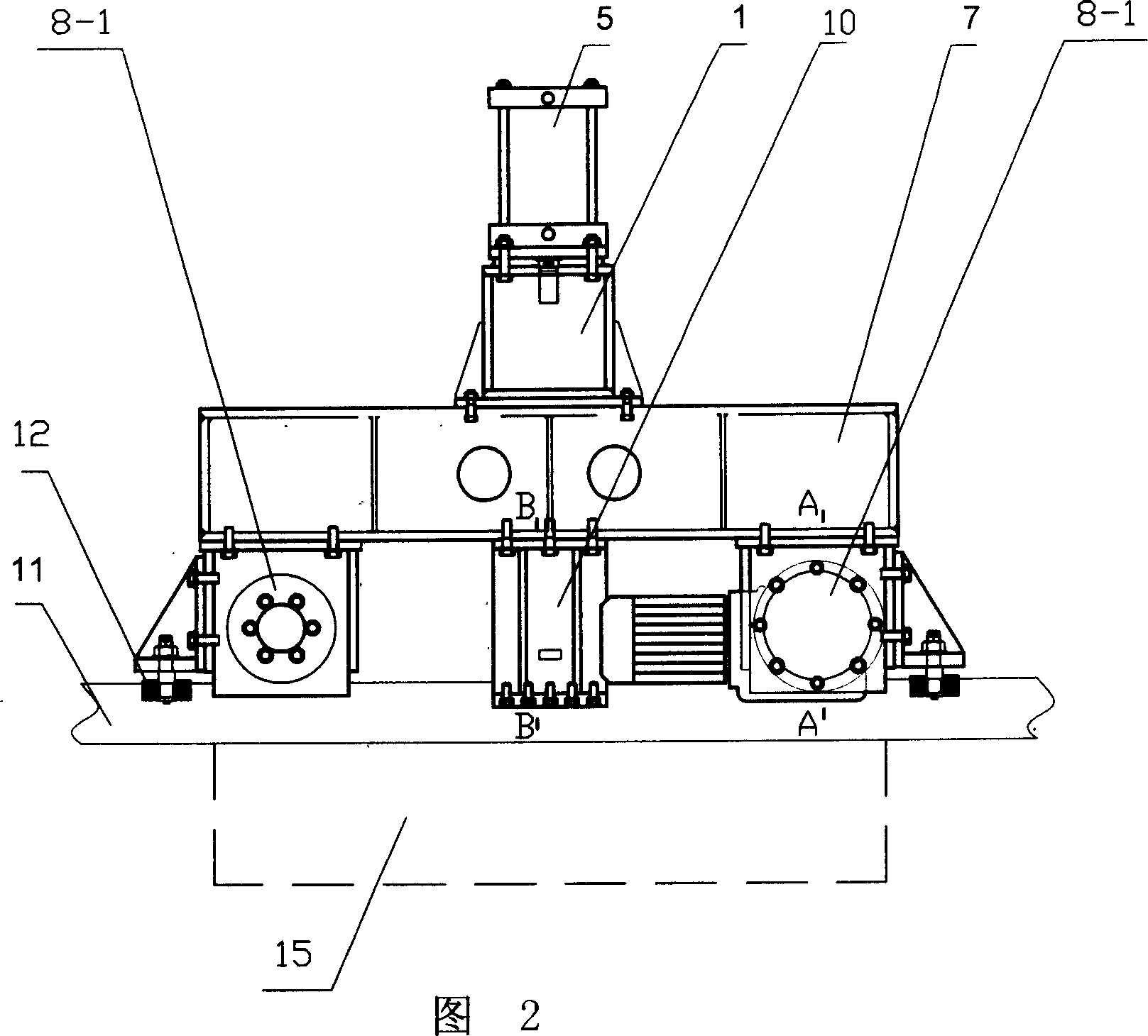
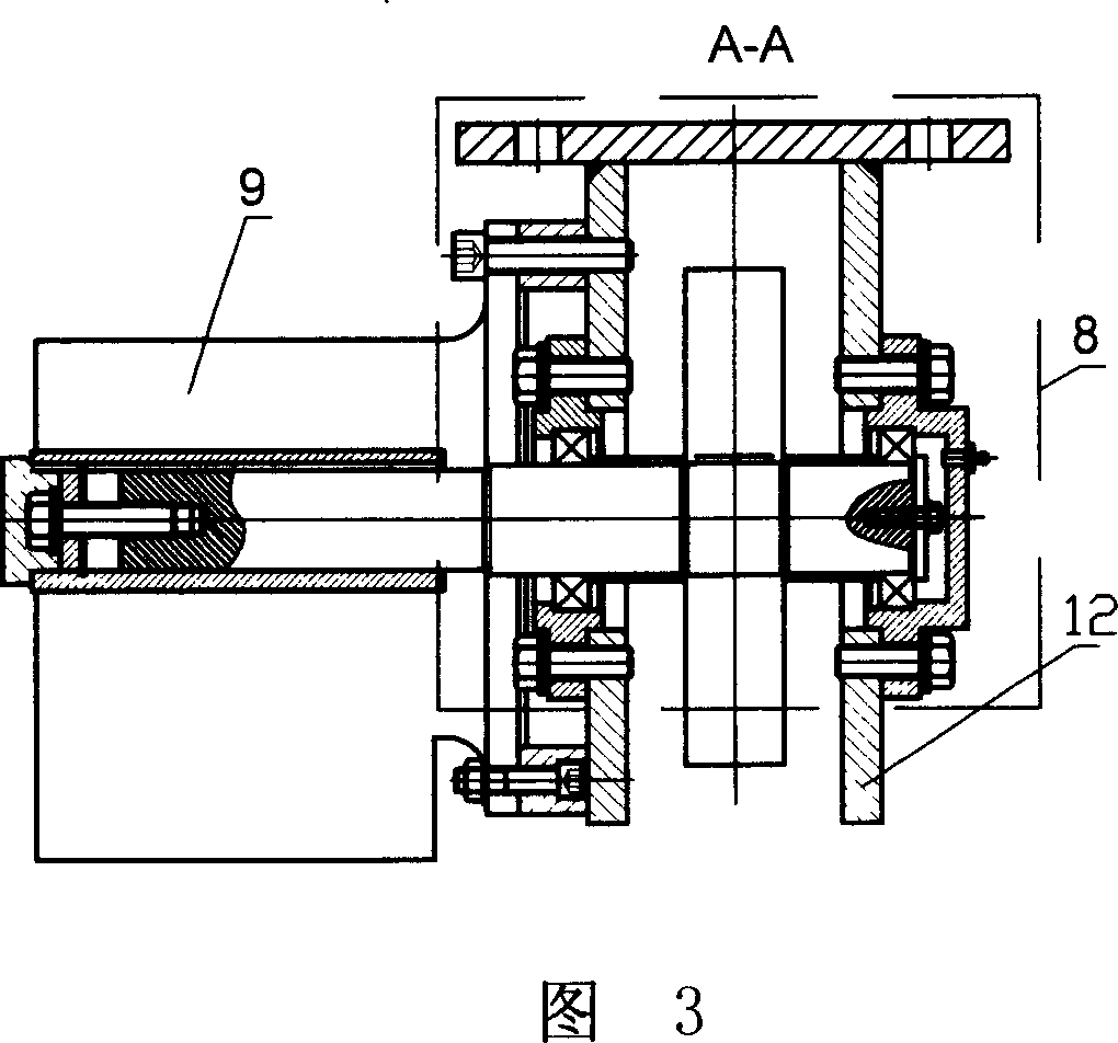
[0015] Specific embodiment three: the beam 1 in this embodiment is fixed on the longitudinal beam 7, and the lower end of the longitudinal beam 7 is fixed on the wheel assembly 8, and the wheel 8-1 on the wheel assembly 8 is arranged on the track 11, and it also It includes a driving device 9, which is a combination of a reducer and a motor, and the output shaft of the motor is connected to the central shaft of the wheel 8-1 through a bevel gear reducer. The assembly machine is set on the track through the wheels, and the wheels are driven by the motor to walk freely, which can solve the trouble of manual carts and reduce the labor expenditure and running time of workers; the bevel gear transmission connection can ensure stable and reliable transmission. Reduce noise.


PUM


Abstract

An electrically pneumatic assembling machine for assembling the U-shaped rib onto the unit plate used for the steel structure of bridge is composed of a transverse beam, a formwork module under said transverse beam, the guide sleeves fixed to said transverse beam, the guide rods in said guide sleeves and connected between formwork module and piston rod of cylinder, and the cylinders fixed to said transverse beam.

Description

technical field [0001] The invention relates to a machine for assembling U-shaped ribs in the manufacturing process of steel box girder plate unit elements of bridge steel structure. Background technique [0002] At present, in bridge steel structure manufacturing enterprises, the U-shaped rib assembly of plate unit elements commonly used is a manual device. The manual U-shaped rib assembly machine has the following disadvantages: ①The template and the beam are welded. For the assembly of different plate units and different ribs, it is very inconvenient to assemble and disassemble the template, so it cannot realize the assembly of ribs of different shapes, which is not conducive to practical use ;②When assembling the plate unit, the compression between the U rib and the surface (bottom) plate is assembled by manual burning of the code plate. The labor intensity of the workers is large and the surface of the rib is damaged, which is time-consuming and laborious and the assemb...

Claims


Application Information

Patent Timeline
Patent Type & Authority Applications(China)
IPC IPC(8): B23P19/04B23Q7/00
Inventor 陈望民陈家菊陈复保林惠蕾
Owner WUCHUAN HEAVY ENG
Why Eureka
Try Eureka