User face protocol stack and head compression method

A user plane and protocol stack technology, applied in digital transmission systems, electrical components, transmission systems, etc., can solve problems such as waste of backhaul bandwidth, transmission efficiency and transmission delay, no details of protocol architecture, low data rate, etc., to achieve Reasonable hierarchical structure and node distribution, improved resource utilization efficiency, and high-speed effects

Active Publication Date: 2007-04-18
HUAWEI TECH CO LTD
View PDF0 Cites 23 Cited by
  • Summary
  • Abstract
  • Description
  • Claims
  • Application Information

AI Technical Summary

Problems solved by technology

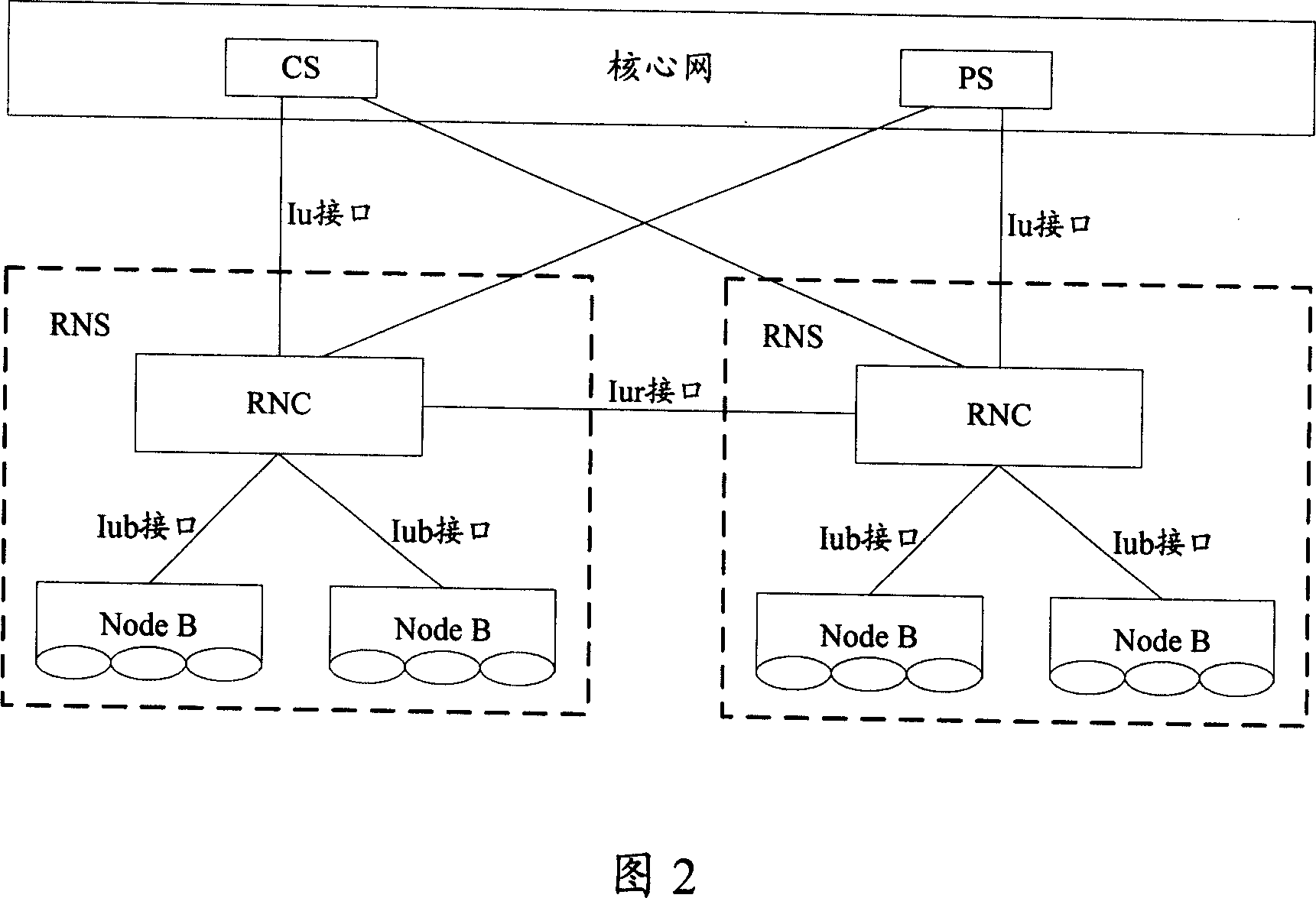
[0010] As can be seen from the above description, the function of header compression in the prior art is implemented in the RNC. Because there are many problems in the existing network, such as high time delay, low data rate, many nodes, and high investment costs, 3GPP's current LTE ( The Long Term Evolution) project is developing an architecture for evolving networks, thus resulting in candidate architectures for two-layer nodes and three-layer nodes as described above
At present, LTE has not proposed any details of the protocol architecture except for the framework architecture, and has not proposed any solution for the header compression method of the evolved architecture.
[0011] In addition, in the future network evolution architecture, the CS domain will disappear, only the PS domain will exist, and the voice will be carried by the PS domain in the form of VOIP (Voice over IP; Voice over IP), which means that the future access network There will be a large number of VOIP RTP packets between the core network, and the header bytes in the RTP packets account for more than 80%, so this will greatly waste the bandwidth, transmission efficiency and transmission delay of the backhaul (backhaul), so A complete solution for header compression needs to be rethought in new network architectures

Method used


Image

  • User face protocol stack and head compression method
  • User face protocol stack and head compression method
  • User face protocol stack and head compression method

Examples


Embodiment Construction

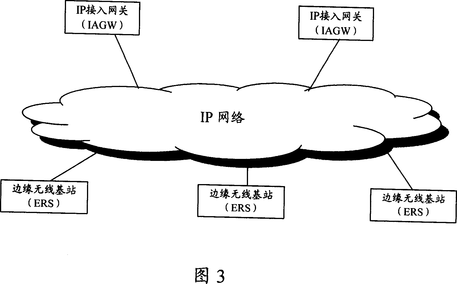
[0053] Referring to FIG. 5 , it shows the user plane protocol stack based on the two-layer node evolution network provided by the present invention. There are only two layers of nodes on the network side, ERS and IAGW.

[0054] The user plane protocol stack includes an IAGW user plane protocol stack, an ERS user plane protocol stack and a user terminal (UE) user plane protocol stack.

[0055] The IAGW user plane protocol stack includes: L1 layer, L2 layer, IP layer and upper layer (Upper Layer);

[0056] The ERS user plane protocol stack includes the L1 layer, L2 layer, IP layer, and high layer that are equivalent to the IAGW user plane protocol stack on the E-I interface side with the IAGW; on the wireless interface side, it includes: wireless (Radio) L1 layer, low layer ( Lower Layer) and header compression (Header Compression, HC) layer;

[0057] The UE user plane protocol stack includes the Radio L1 layer, the lower layer and the header compression layer that are equival...


PUM


Abstract

The invention discloses a user interface protocol stack, applied to radio evoluted networkin two-layer node structure, comprising IP access gateway (IAGW) user interface protocol stack, edge radio station (ERS) user interface protocol stack and uer end (UE) user interface protocol stack, where the IAGW user interface protocol stack comprises: layer L1, layer L2, IP layer and higher layer; the ERS user interface protocol stack comprises equivalent layer L1, layer L2, IP layer and higher layer on E-I interface side between it and IAGW; the radio interface side comprises: radio layer L1, lower layer and head compression layer; the UE user interface protocol stack comprises equivalent radio layer L1, lower layer and head compression layer to those on ERS radio interface side. And the invention also discloses a head compressing method in the two-layer node structure, implementing head compression of air interface data packet between ERS and UE.

Description

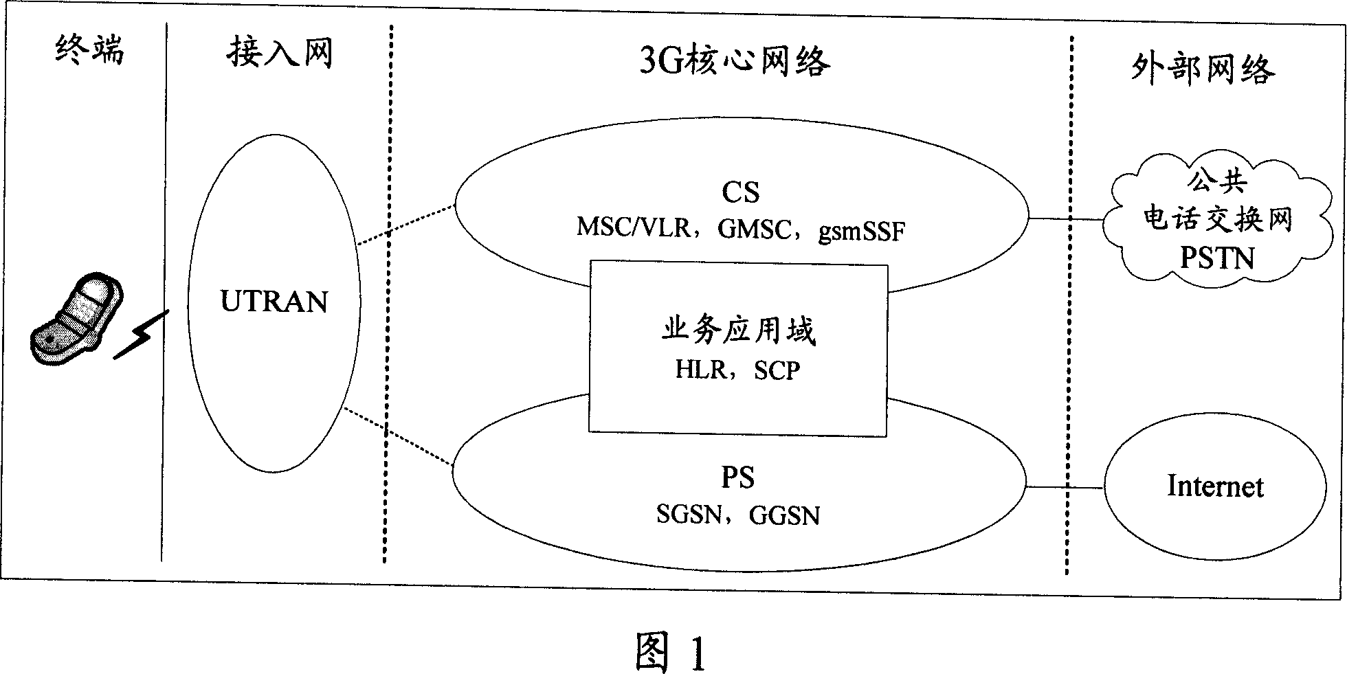
technical field [0001] The invention relates to the field of wireless communication, in particular to an evolution network user plane protocol stack with a two-layer node structure, and a data packet header compression method applied to the user plane protocol stack. Background technique [0002] The Universal Mobile Telecommunications System (UMTS) is a third-generation mobile communication system using the WCDMA air interface technology, and the UMTS system is usually also called a WCDMA communication system. The UMTS system adopts a structure similar to that of the second generation mobile communication system, including a radio access network (Radio Access Network, RAN) and a core network (CoreNetwork, CN). Among them, the wireless access network is used to handle all wireless-related functions, while the CN handles all voice calls and data connections in the UMTS system, and realizes switching and routing functions with external networks. The CN is logically divided in...

Claims


Application Information

Patent Timeline
Patent Type & Authority Applications(China)
IPC IPC(8): H04L29/06H04L12/56
Inventor 罗龙
Owner HUAWEI TECH CO LTD
Why Eureka
Try Eureka