Wire grid polarizer and manufacturing method of the same

A technology of wire grid polarization and manufacturing method, which can be used in polarization elements, diffraction gratings, nonlinear optics, etc., and can solve the problem that visible light cannot obtain sufficient polarization degree.

Active Publication Date: 2007-04-25
ASAHI KASEI KK
View PDF5 Cites 39 Cited by
  • Summary
  • Abstract
  • Description
  • Claims
  • Application Information

AI Technical Summary

Problems solved by technology

[0005] However, the above-mentioned wire grid polarizing element has the problem that resonance in the visible light spectrum must be taken into account when used as a diffraction grating, and a sufficient degree of polarization cannot be obtained in the low-wavelength region of visible light.

Method used


Image

  • Wire grid polarizer and manufacturing method of the same
  • Wire grid polarizer and manufacturing method of the same
  • Wire grid polarizer and manufacturing method of the same

Examples


Embodiment Construction

[0035] With reference to the embodiments of the present invention, (1) the wire grid polarizing plate of the present invention, (2) the method for obtaining the resin matrix having lattice-shaped protrusions of the present invention, and (3) the wire grid polarizer of the present invention The sequence of the sheet manufacturing method will be described in detail.

[0036] (1) Wire grid polarizer of the present invention

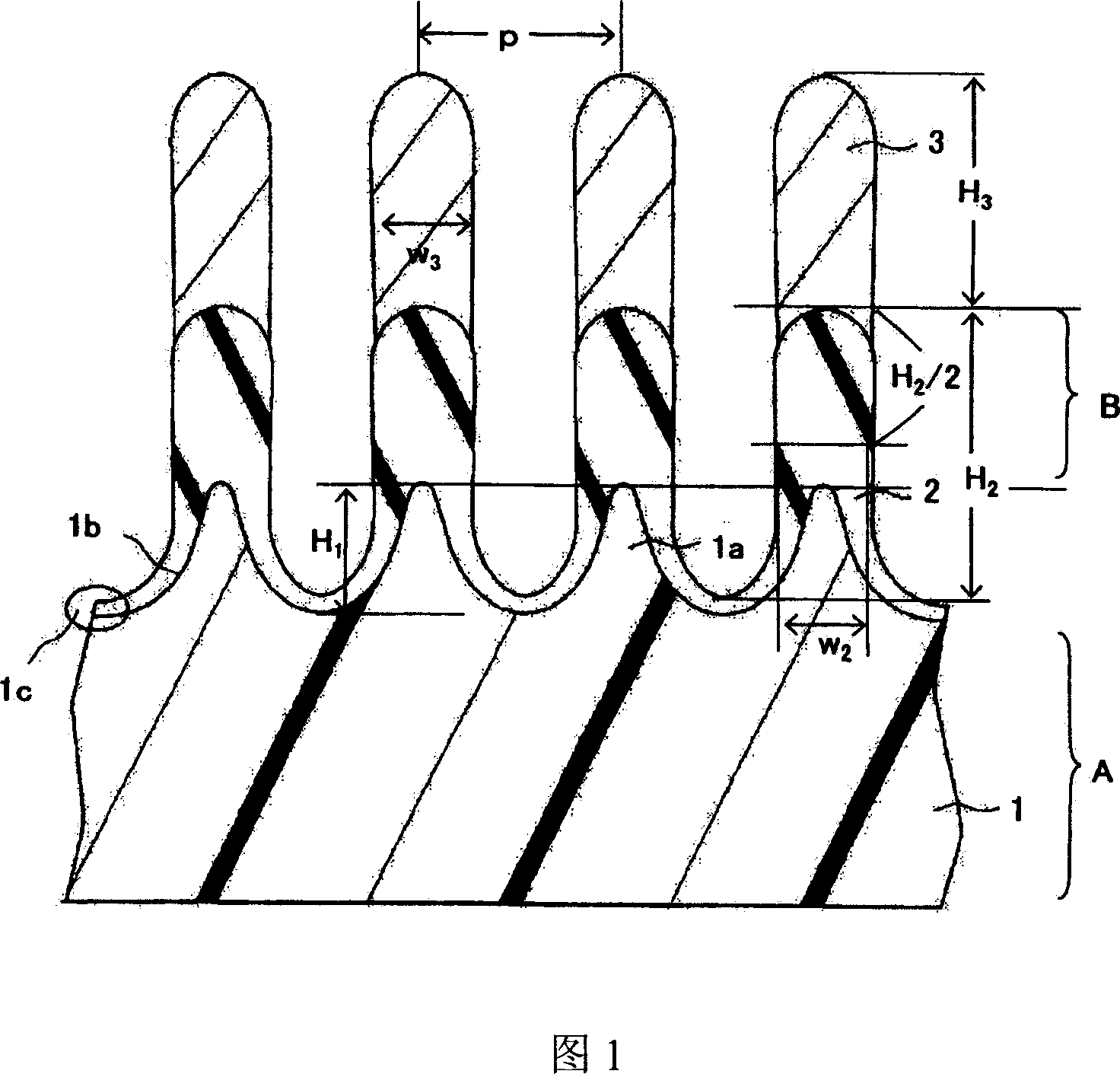
[0037] FIG. 1 is a schematic cross-sectional view showing a part of a wire grid polarizing plate according to an embodiment of the present invention. The wire grid polarizing plate shown in FIG. 1 is mainly composed of a resin substrate 1 (hereinafter also referred to as resin substrate 1) having a lattice-shaped convex portion, and a lattice-shaped convex portion 1a (hereinafter also referred to as convex portion 1a) arranged to cover the resin substrate. Part 1a) and at least a part of the side surface 1b are composed of a dielectric layer 2 and a metal w...


PUM

PropertyMeasurementUnit
heightaaaaaaaaaa
thicknessaaaaaaaaaa
glass transition temperatureaaaaaaaaaa

Abstract

A wire grid polarizer has mainly a resin substrate (1) having grid-shaped convex portions (1a), a dielectric layer (2) provided to cover the grid-shaped convex portions (1a) of the resin substrate (1) and at least part of side faces (1b) of the portions, and metal wires (3) provided on the dielectric layer. The wire grid polarizer has a microstructural concavo-convex grid structure having grid-shaped convex portions, is not limited in structure, and has both the excellent degree of polarization and excellent transmittance over a wide range in the visible region.

Description

technical field [0001] The present invention relates to a wire grid polarizing plate, a method for manufacturing the same, and a liquid crystal display device using the same. Background technique [0002] Due to the development of photolithography in recent years, it has become possible to form a pattern of a fine structure having a pitch at the level of the wavelength of light. A member and a product having such a pattern with a very small pitch are widely used not only in the semiconductor field but also in the optical field, and are very useful. [0003] For example, a wire grid formed by arranging conductive wires made of metal or the like at a specific pitch, as long as the pitch is relatively small (for example, 1 / 2 or less) compared to incident light (for example, the wavelength of visible light is 400nm to 800nm) , then almost all the light of the electric field vector component vibrating parallel to the wire is reflected, and the light of the electric field vector ...

Claims


Application Information

Patent Timeline
Patent Type & Authority Applications(China)
IPC IPC(8): G02B5/30G02F1/1335
CPCG02F2001/133548G02B5/3058G02F1/133548G02B5/18G02B5/30
Inventor 山木宏佐藤祐辅生田目卓治河津泰幸
Owner ASAHI KASEI KK
Why Eureka
Try Eureka