

Manufacture method for diode light-emitting device and its structure
A technology for a light-emitting device and a manufacturing method, which is applied to the manufacturing of semiconductor/solid-state devices, electrical components, and electrical solid-state devices, etc., can solve the problems of complex manufacturing process and low heat dissipation efficiency of packaging structure, and achieves improved heat dissipation efficiency and increased air tightness. , the effect of good heat dissipation efficiency
- Summary
- Abstract
- Description
- Claims
- Application Information
AI Technical Summary
Problems solved by technology
Method used
Image

Examples
Embodiment Construction
[0091] In order to further illustrate the purpose, structural features and functions of the present invention, the detailed descriptions are as follows in conjunction with relevant embodiments and accompanying drawings:
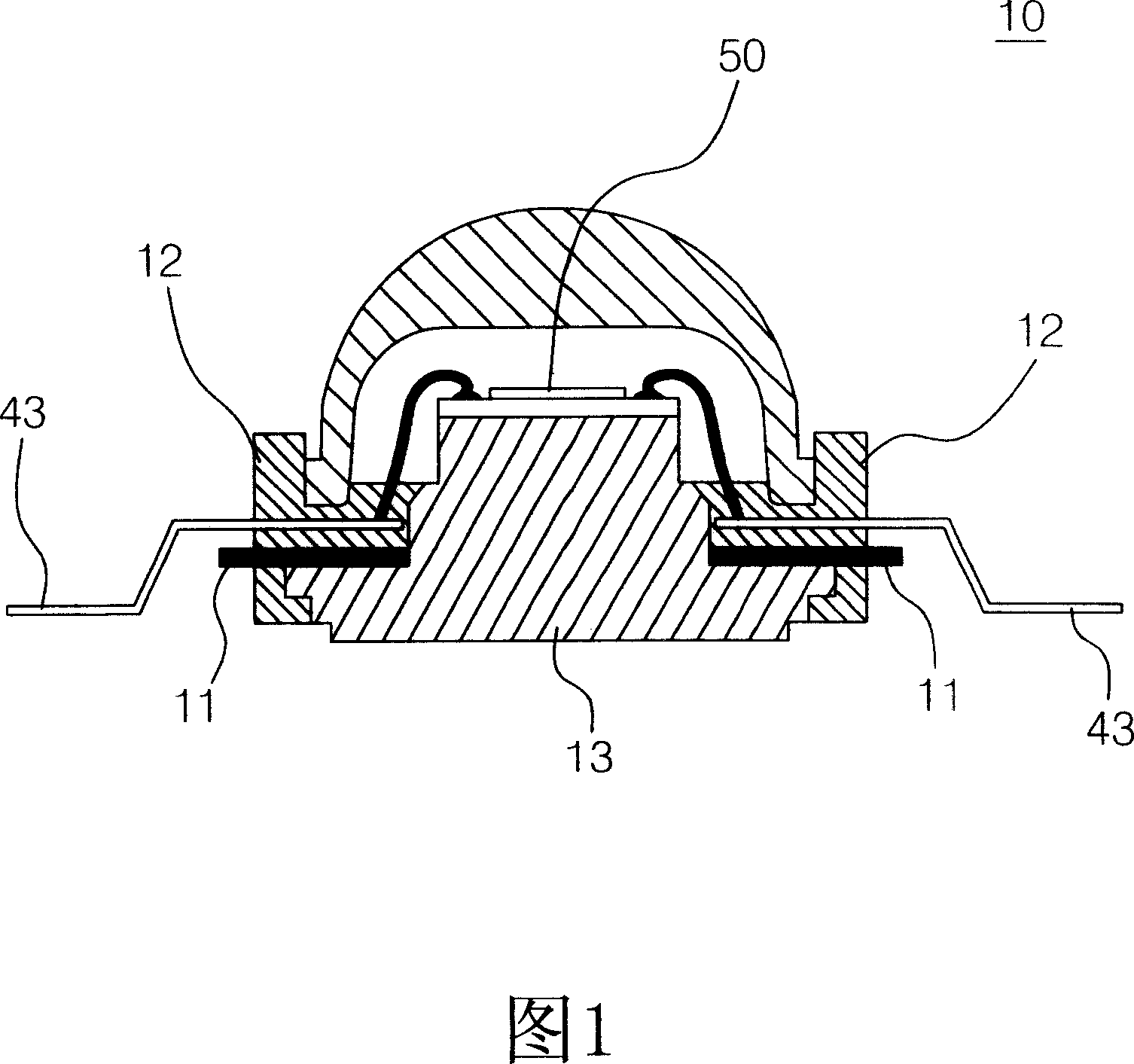
[0092] The present invention is a method for manufacturing a diode light-emitting device 30 and its structure, wherein the structure of the diode light-emitting device 30 is to use a metal material with good thermal conductivity to manufacture the body 41, 41' of the diode light-emitting device 30, so as to greatly increase the heat dissipation area , so that the diode chip 50 of the diode light emitting device 30 can obtain a better heat dissipation effect during operation.
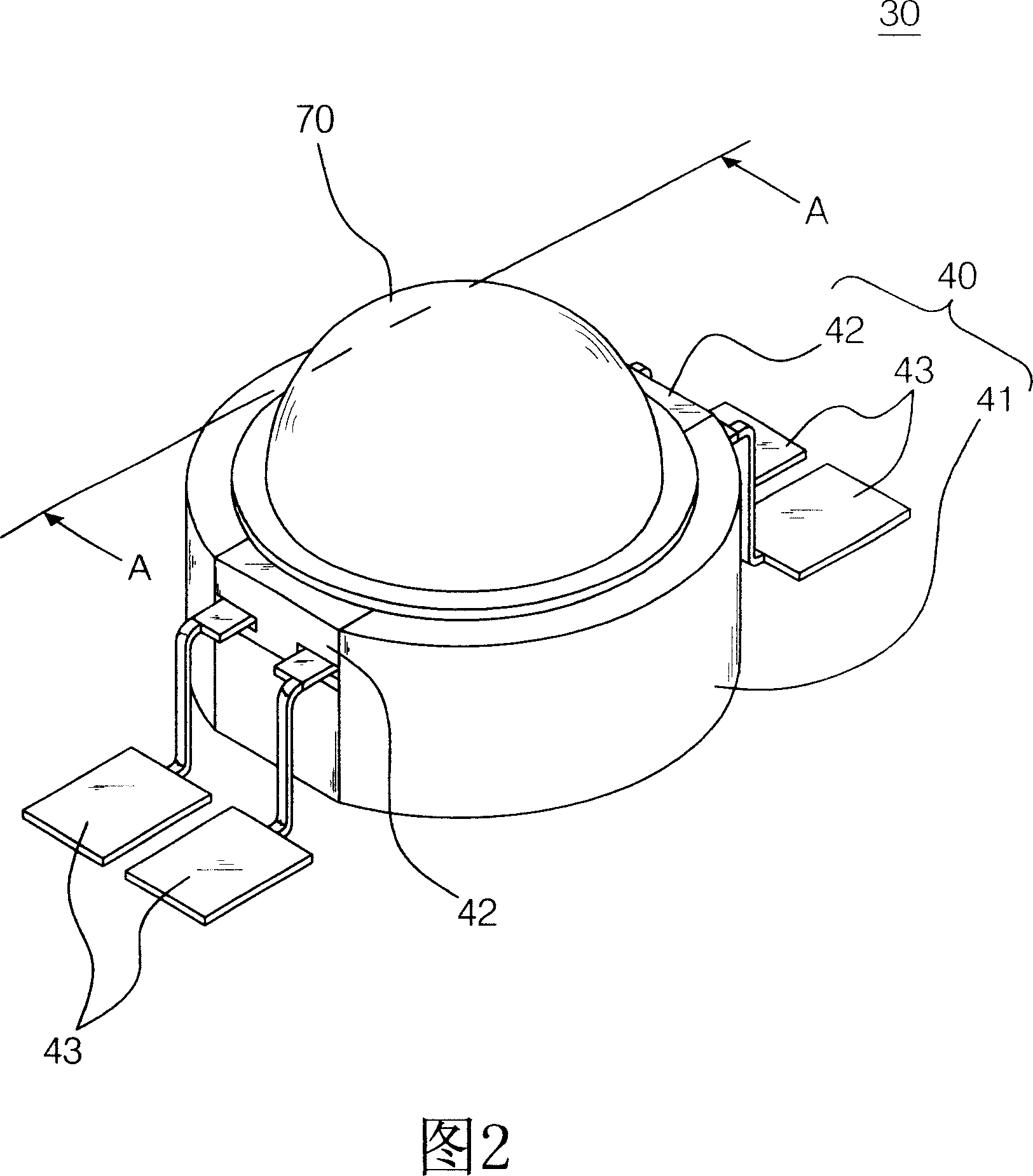
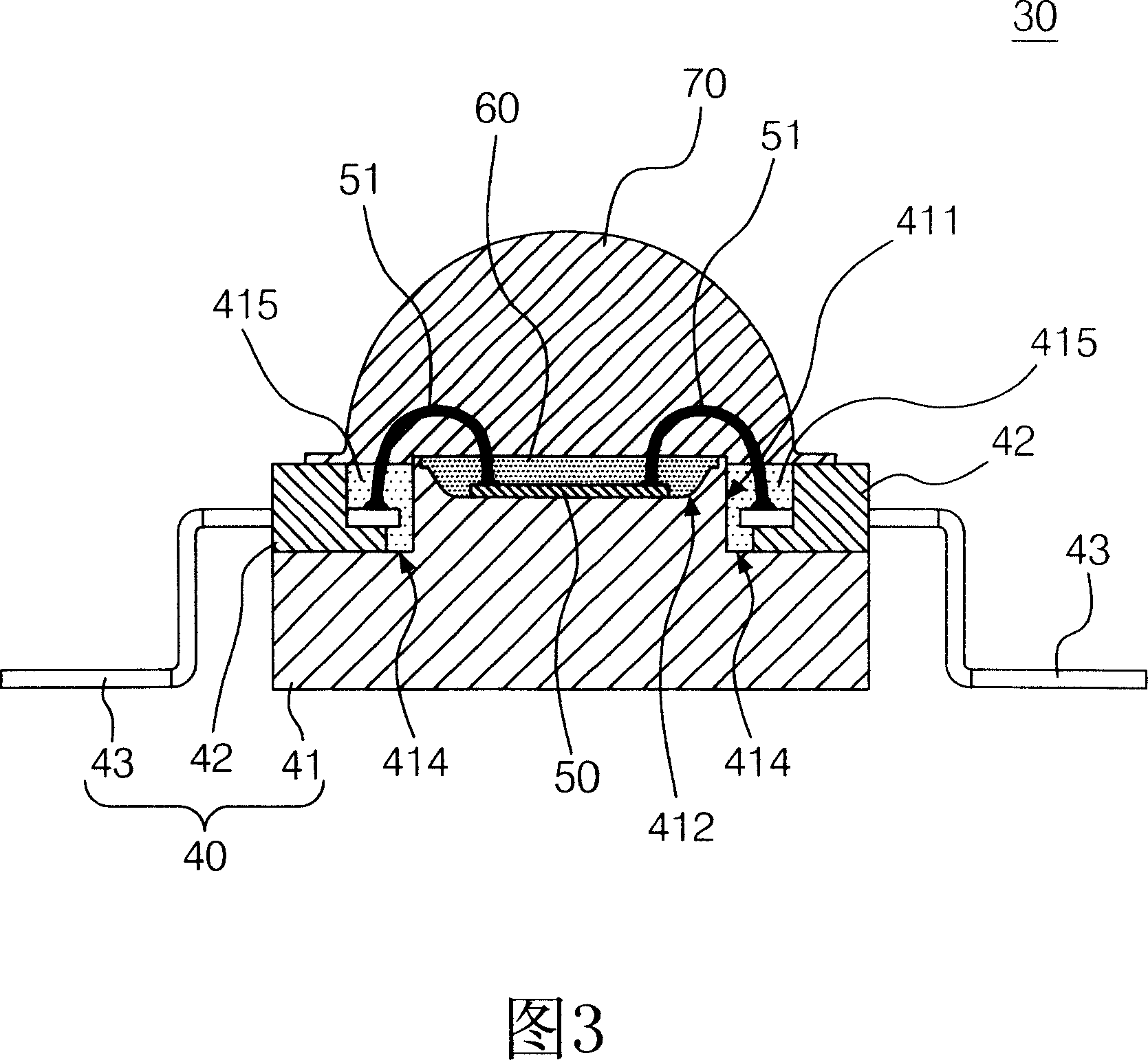
[0093] FIG. 2 is a stereoscopic implementation diagram of a diode light emitting device 30 of the present invention. As shown in FIG. 3 , it is a cross-sectional implementation diagram of a diode light emitting device 30 of the present invention along the line A-A of FIG. 2 . The diode...
PUM
 Abstract
Description
Claims
Application Information